A DIY CO2 Monitor for the Basement Office
My office is in the basement, and the only outside air it gets comes through one tiny window. It doesn’t take long for it to feel stuffy in there, and I wanted to see if it’s getting bad enough to actually affect me. High CO2 doesn’t really hurt you at typical office levels, but it does make you tired and foggy, which isn’t great when you’re trying to think.
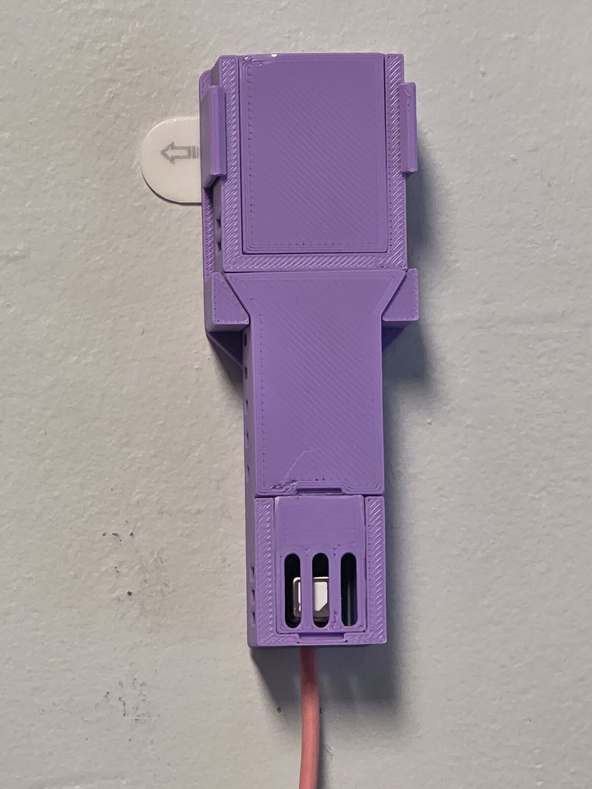
There are plenty of CO2 monitors out there, but most of the cheap ones aren’t really measuring CO2 at all, and the good ones are expensive for something that only needs to report one number to Home Assistant. So I built one with a real sensor for under C$30 in parts with a nice 3D printed case.
Why not just buy one?
A few things ruled out the off the shelf options:
- A lot of cheap “CO2” sensors (SGP30, CCS811, ENS160) don’t measure CO2. They measure VOCs and estimate CO2 from them, which they call “eCO2”. It’s a guess, and not a good one. A real sensor uses NDIR or photoacoustic sensing - something like the Sensirion SCD4x, SCD30, or Senseair S8.
- Almost every real CO2 sensor has automatic self calibration turned on. It assumes the sensor sees fresh outdoor air (about 400 ppm) once a week or so, and quietly treats the lowest reading it sees as 400. In my basement, it’s unlikely it sees enough fresh air to calibrate properly, so it would slowly drift towards incorrectly lower readings. Few ready made CO2 monitors let you control the calibration, but ESPHome does.
- I went with the SCD41 over the cheaper SCD40 because its accuracy is rated up to 5000 ppm instead of 2000. A stuffy basement can go over 2000, and the difference was a few dollars.
What I looked at before deciding to build one (prices from September 2026):
- IKEA ALPSTUGA (C$49.99) has a real Sensirion sensor in it, but it’s Matter over Thread, and I don’t have a Thread border router yet. It’s not quite as accurate or configurable, but for the price it’s quite tempting.
- SwitchBot Meter Pro CO2 (about C$68 on sale) - I couldn’t confirm what sensor it actually uses, and it’s Bluetooth.
- Apollo AIR-1 (about US$110 plus duties) is a great ESPHome device, but it uses an SCD40 at 4-5 times the cost of building one.
- Aranet4 (C$239) and the AirGradient ONE (C$320 kit) are both good, but overkill for just CO2.
- Airthings View Plus - close to C$400, and cloud based. They seem to make nice hardware, but I’m definitely not their target audience.
The original plan was to put the sensor on a spare Cheap Yellow Display (an ESP32 with a touchscreen) and show a colour coded number on my desk. That display ended up getting used for something else, so I switched to a plain D1 mini with no display. The readings show up on the screens I already have through Home Assistant, which is honestly fine.
Parts
- A Sensirion SCD41 breakout board from AliExpress, about C$27. It’s tiny - 21.7 x 15.8mm. The sensor is laser marked SCD41 with a DataMatrix code like Sensirion’s own parts, so it looked genuine. More on how to check that below.
- A Wemos D1 mini (ESP8266) MCU I’ve had lying in a drawer for years, with no headers soldered on.
- 4 wires, soldered straight into both boards: 3V3, GND, D2 for SDA and D1 for SCL.
- A USB wall adapter and a micro USB cable.
- A 3D printed case.
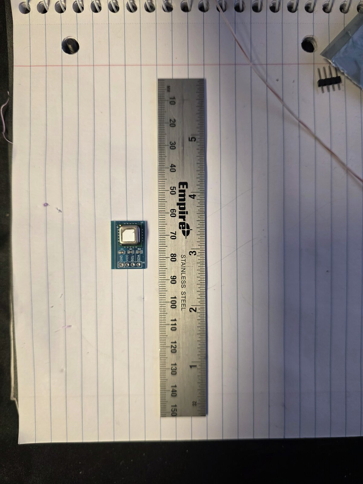
There’s no perfboard on purpose. Mounting both boards on one piece of perfboard would conduct the ESP’s heat straight to the sensor, which is the exact problem the case is designed to avoid.
An important tip for the sensor - that white sticker on the top might look like a protective cover you’re supposed to remove. That was my first thought, and I’m glad I looked it up first. It’s not a removable cover - it’s a filter that protects the sensor from dust and contaminants while letting air flow through. Remove it and the sensor is trashed.
The heat problem
The MCU runs a few degrees warm with Wi-Fi on, and how warm changes as the Wi-Fi activity changes. That doesn’t really affect the CO2 reading itself - the SCD41 compensates internally with its own temperature and humidity sensor, and Sensirion’s datasheet says the temperature offset setting doesn’t impact the accuracy of the CO2 output. But it does throw off the temperature and humidity it reports, and those are useful readings too. A steady offset can be calibrated out. One that fluctuates depending on the activity of another device can’t.
Sensirion publishes a design-in guide for the SCD4x that covers this, and boils down to:
- Put a large opening right at the sensor, with as little dead air inside as possible, and keep the sensor’s air sealed off from the rest of the device.
- Put the sensor in the lowest, coldest part of the device, as far from the microcontroller and Wi-Fi as possible.
- Keep it out of drafts and sun, and don’t cover the membrane.
Most DIY builds I’ve seen stick the sensor right on top of the ESP in a little box, which is about the worst case on every one of those points.
Sealing the sensor’s air off matters, because drafts will throw off the reading. With the D1 sitting above the sensor, its warm air rising could turn the whole thing into a little chimney, making a constant draft over the sensor. This case solves that by leaving only a small hole for the wires, and sealing that with hot glue.
Designing the case with AI
I didn’t design this case. At least not in the traditional sense.
I described what I needed to Claude Code and it wrote the OpenSCAD. OpenSCAD is awesome for this kind of part because the whole model is just code with parameters, and it turns out that also makes it about the perfect CAD tool for an AI. It can’t drag things around with a mouse, but it can write and rewrite code all day.
The part that makes it actually work is that it can see what it made. It runs OpenSCAD headless to render PNGs from whatever angle it wants, looks at them, and fixes things before I ever see them. Each render takes under a second. When it needs to check how two parts fit, it cuts the model in half in a scratch file and renders the cross section. All I had to give it was a photo of the sensor next to a ruler, Sensirion’s design-in guide, and what I wanted. Claude came back with a list of caliper measurements to take and got to work.
Three options to start
A few minutes later it came back with three concepts, each with a render:
- A - one stick, with the sensor in a pod at the bottom, an open gap for room air, and the ESP in a chamber at the top.
- B - two separate boxes joined only by the wires. The best thermal isolation, but two loose things to mount.
- C - one compact box. The neatest looking, but it has the same problem many designs share where the MCU is too close to the sensor.
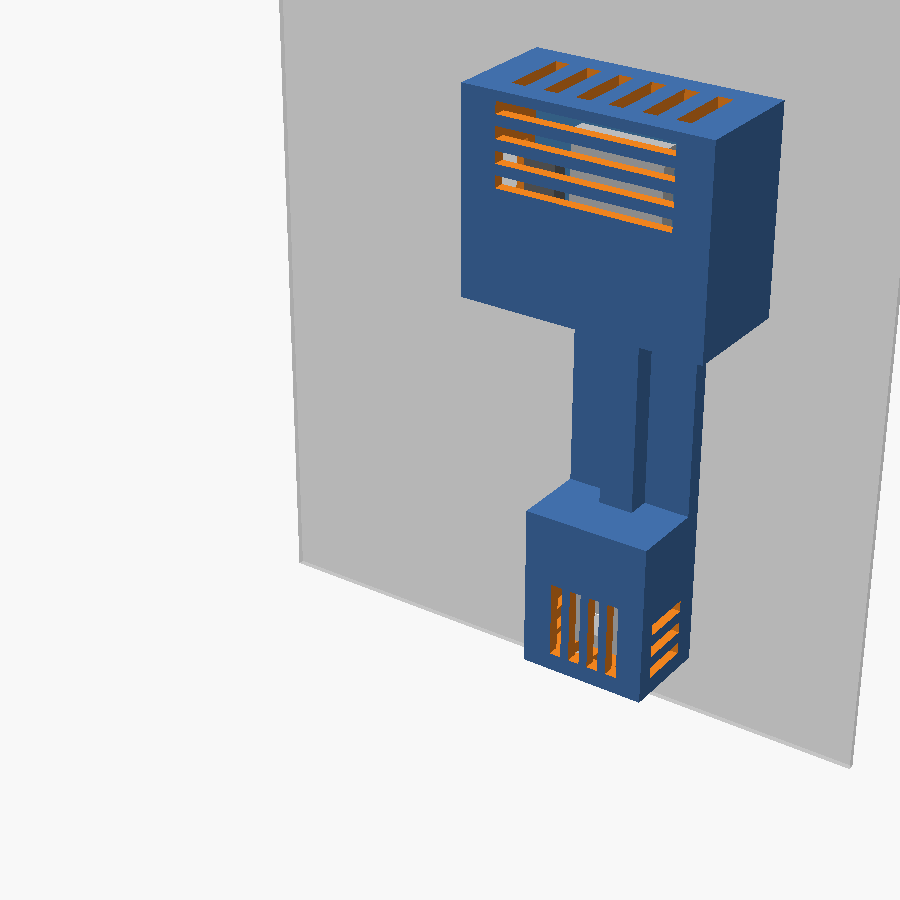
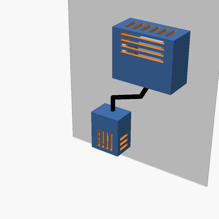
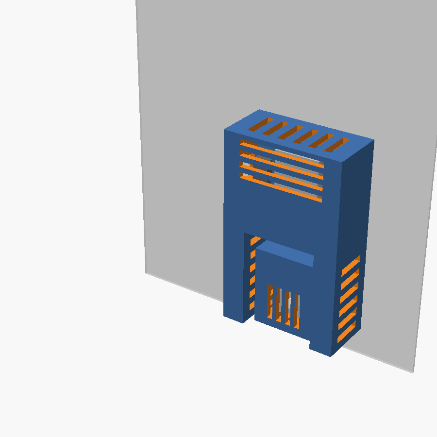
I picked A. Then I wanted the USB cable to come out the bottom, and its first attempt at that decided the best way to do that would be to still have the D1’s USB facing the side, but make the case bigger and tell me to buy a right angled cable.
Instead, I pointed out to Claude that things can rotate, and it might get better results with the USB port facing down. Once it rotated the MCU, everything lined up better and Claude added a channel down the back for the cable to run through, with plenty of space for almost any USB cable. Its rendering of the cable is…interesting, but it works nicely.
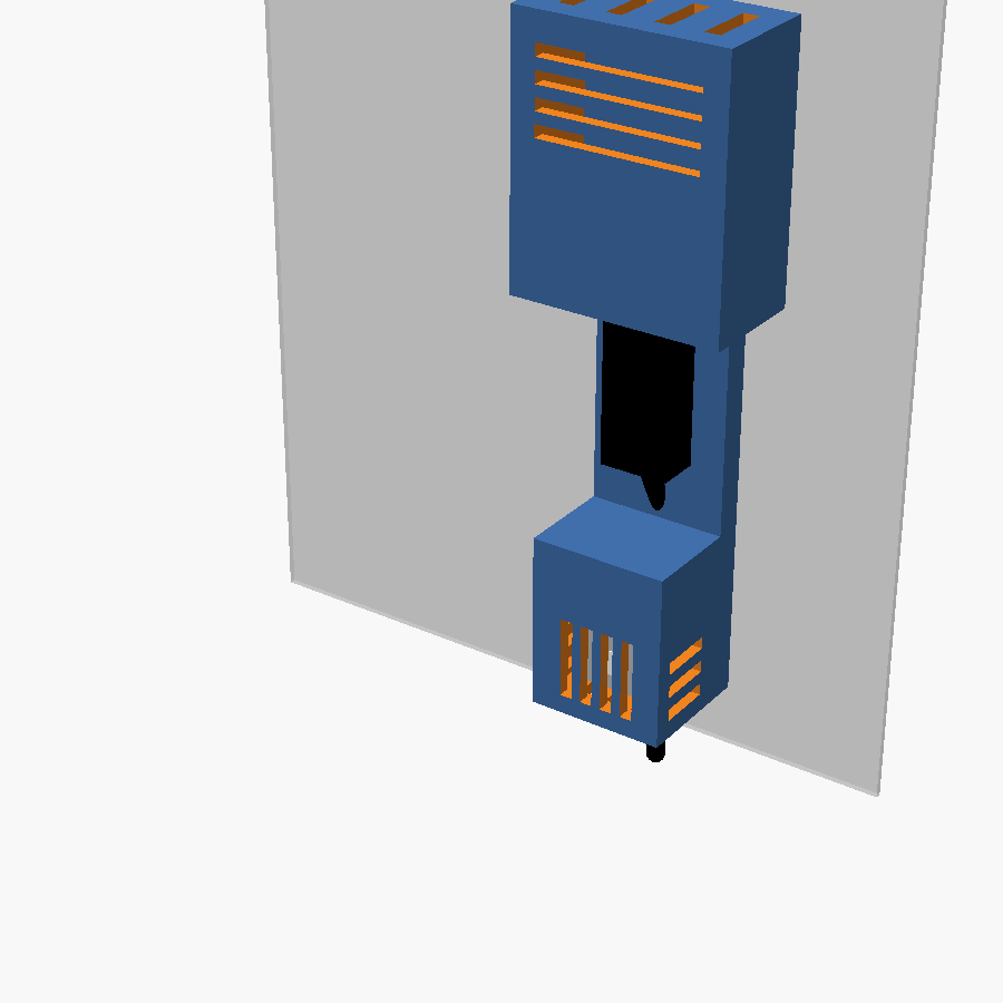
Printable version
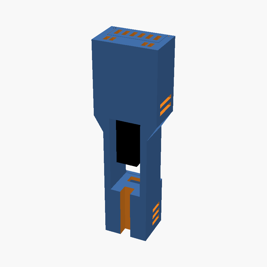
Under an hour after I first asked, it had a printable model: the body (printed on its back, so the flat back can take double sided tape), a lid for the sensor pod and a lid for the D1, both sliding down into 45 degree tongue and groove rails, and no supports needed. It also made small test slices of each critical fit so I could check them before printing the whole thing.
It listed the things it couldn’t tell from photos - whether the ESP-12’s antenna was flush with the end of the D1, whether the back of the D1 was clear where a stop pushed on it, whether the USB socket overhung the board edge, and whether anything stuck out of the back of the sensor board. I answered all four just by looking at the boards and it made any necessary adjustments.
Where I had to catch it
It’s not magic, and it got some things wrong.
The first one was easy to catch before printing. The lid for the sensor has ribs that push down on the top edge of the PCB, so the sensor is held in place. The lid slides on from the center into rails. Which is a great design, except for the solid wall the ribs have to pass through on the way. Claude was smart enough to check for interference in the middle where you put the lid to start sliding it on, and in its final resting place, but not the path in between.
When I pointed that out, it came up with a different and worse design by simply removing the material that got in the way. That left a wall held only by its bottom edge that broke off easily on the first print. I had to tell it to make that wall part of the lid itself. That also made the soldering easier, since the wires have to pass through holes in the case before soldering, and that moves one hole to the lid where it can be slid out of the way. Now that we’ve done that in one project, it’s saved instructions to check for that next time, so it just keeps improving as we encounter issues like that.
I also didn’t like the wires and plug just dangling in the open gap between the two halves, so it added a cover for that section that snaps in with little flex fins, a pattern from an earlier project.
The first full print was a test that everything fit and worked well. It found a few issues:
- The previously mentioned sensor wall breaking off easily. To be fair to Claude, I missed the issue too before hitting print.
- The sensor board sat 0.7mm further out than the model, so it got recessed.
- The grilles printed messy, with stringing and blobs around the narrow strips between the slots. Wider bars fixed it, and the front slots on the D1 lid weren’t needed anyways.
- The wire holes became 5mm circles - less airflow between the chambers, and stronger walls.
- The cable groove got a rounded top to get rid of a stress point and a big flat overhang.
Each round of changes took only a few minutes. The next print fit perfectly. The only quirk is that the D1 lid pops off pretty easily, but it faces up so it can’t slide off on its own, so I’m fine with that.
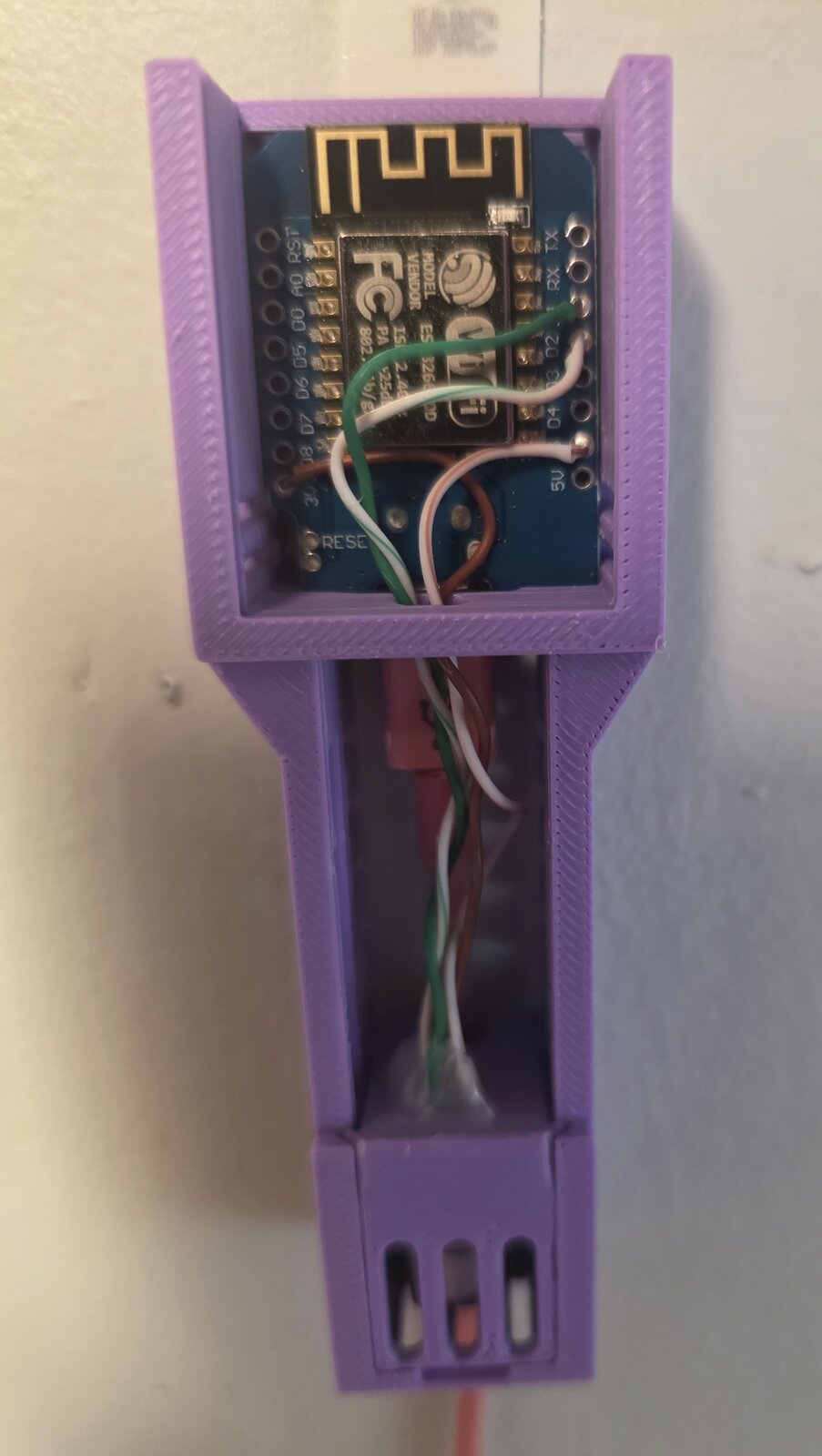
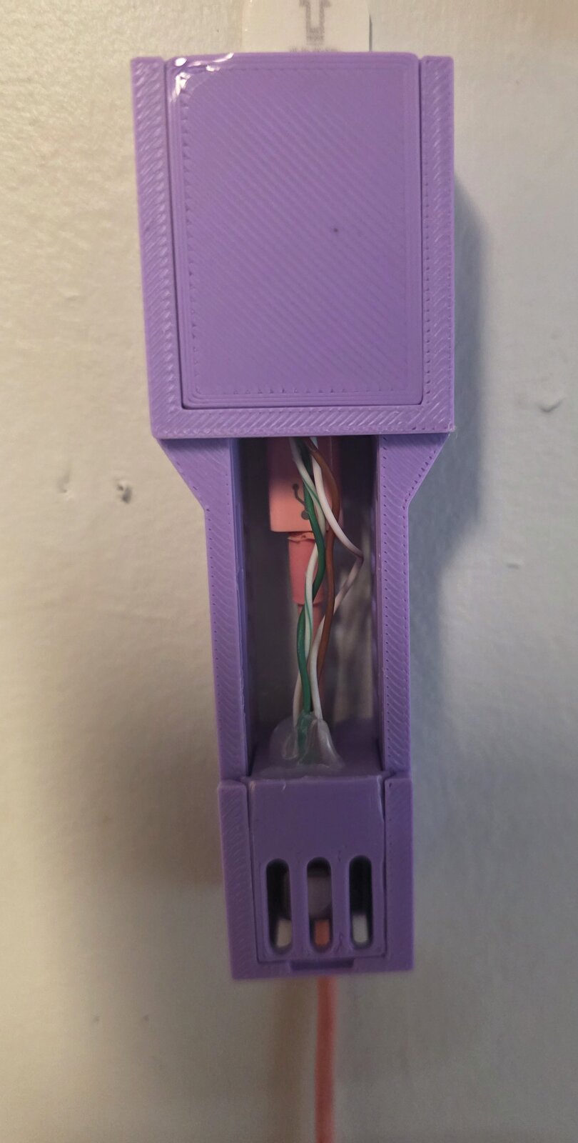
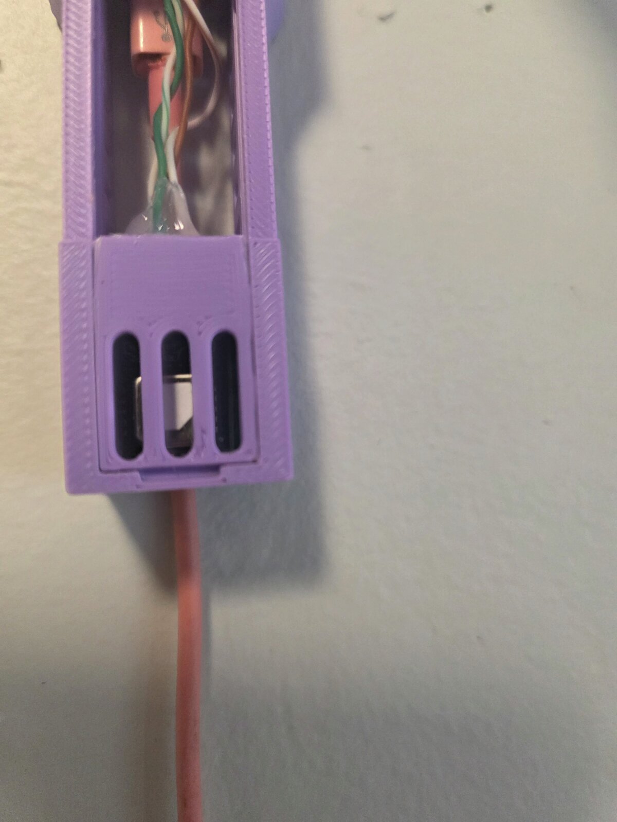
From first request to a case that fits was less than a day, and most of that was happening in the background while I did other things. I didn’t write a line of OpenSCAD. My time went into deciding what I wanted and looking critically at what came off the printer, and none of it into fighting with CAD.
My own mistake
The plan was to stick the flat back to the wall with double sided tape or 3M Command strips. A day after the case was done, I realized that doesn’t work. Calibrating the sensor means taking it outside, and that isn’t a one time job.
I didn’t want to reprint the case, because it would require desoldering the wires and pulling out the hot glue. Instead, I had Claude design a bracket for it. Literally all it took to fix was a single prompt:
For the co2 sensor case, I just realized an oversight I made. It needs to go outside once in awhile to be calibrated. Which means mounting it with 2 sided tape or stickers isn’t great, and I still want it on the wall. It’s too late to change the case without having to desolder and rewire everything. Can you design a bracket I can attach to the wall with 2 sided tape that the case will snap into?
I left Claude alone for a little bit, and it spit out a bracket that the existing case can clip into, making sure to avoid blocking any air vents and using the wider top to its advantage to support the weight there. It fit perfectly on the first try, and the clips have just the right pressure to easily pull out without falling out.
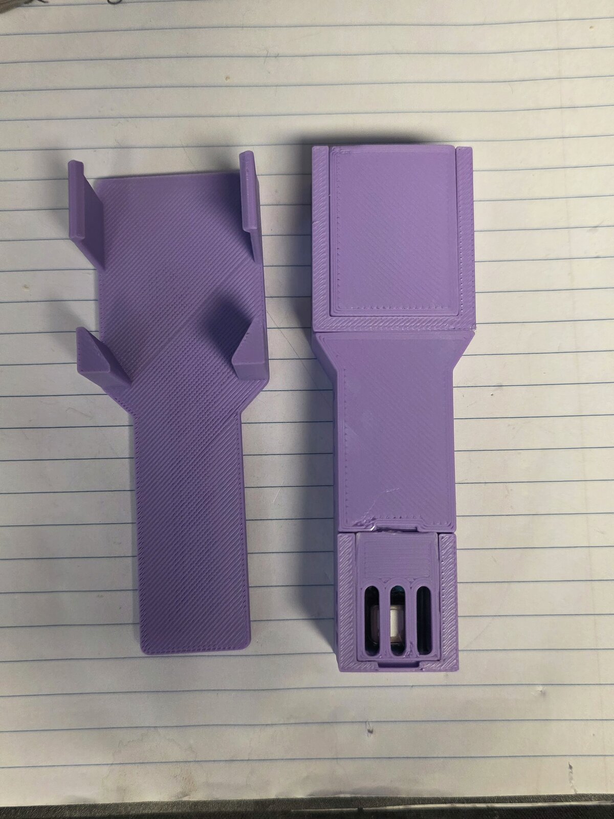
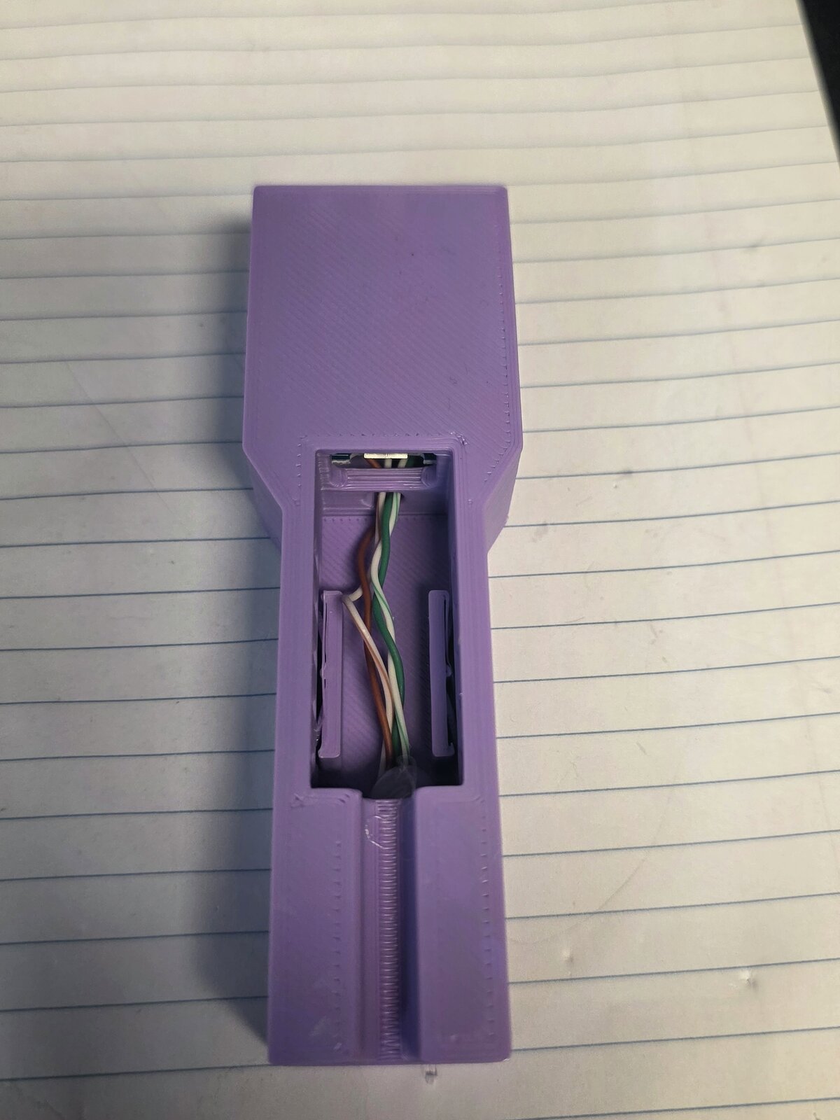
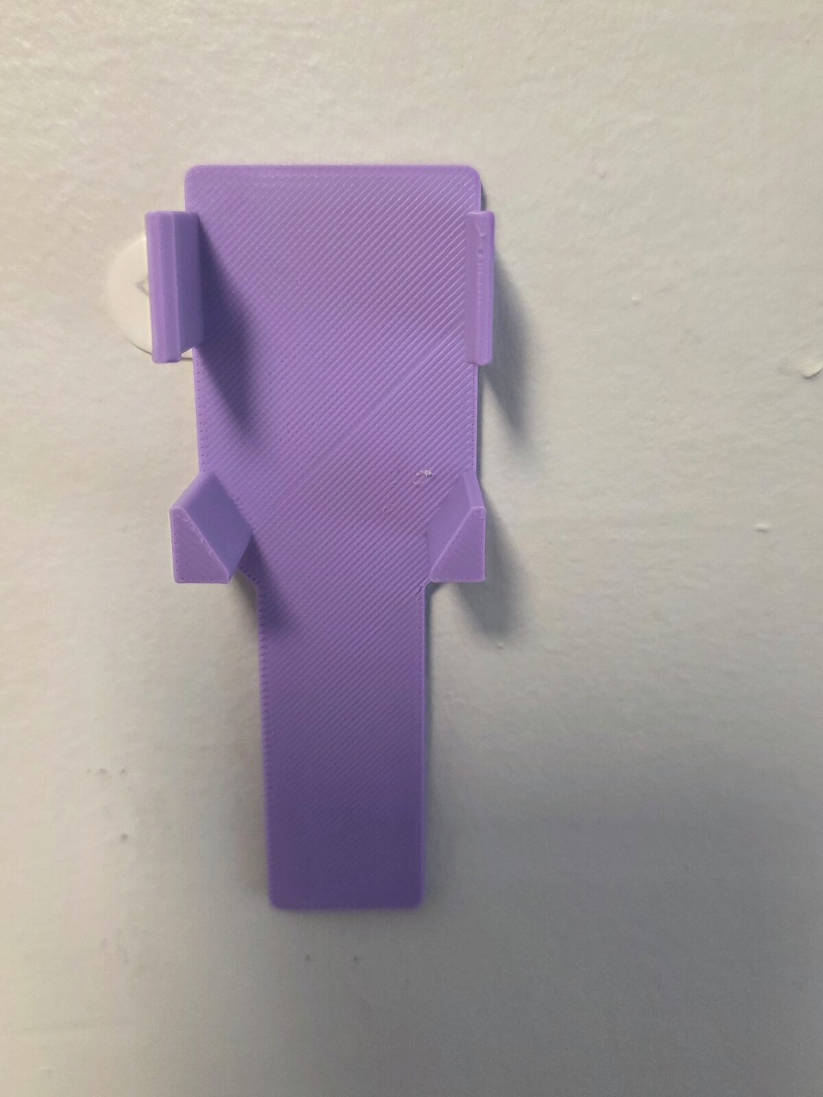
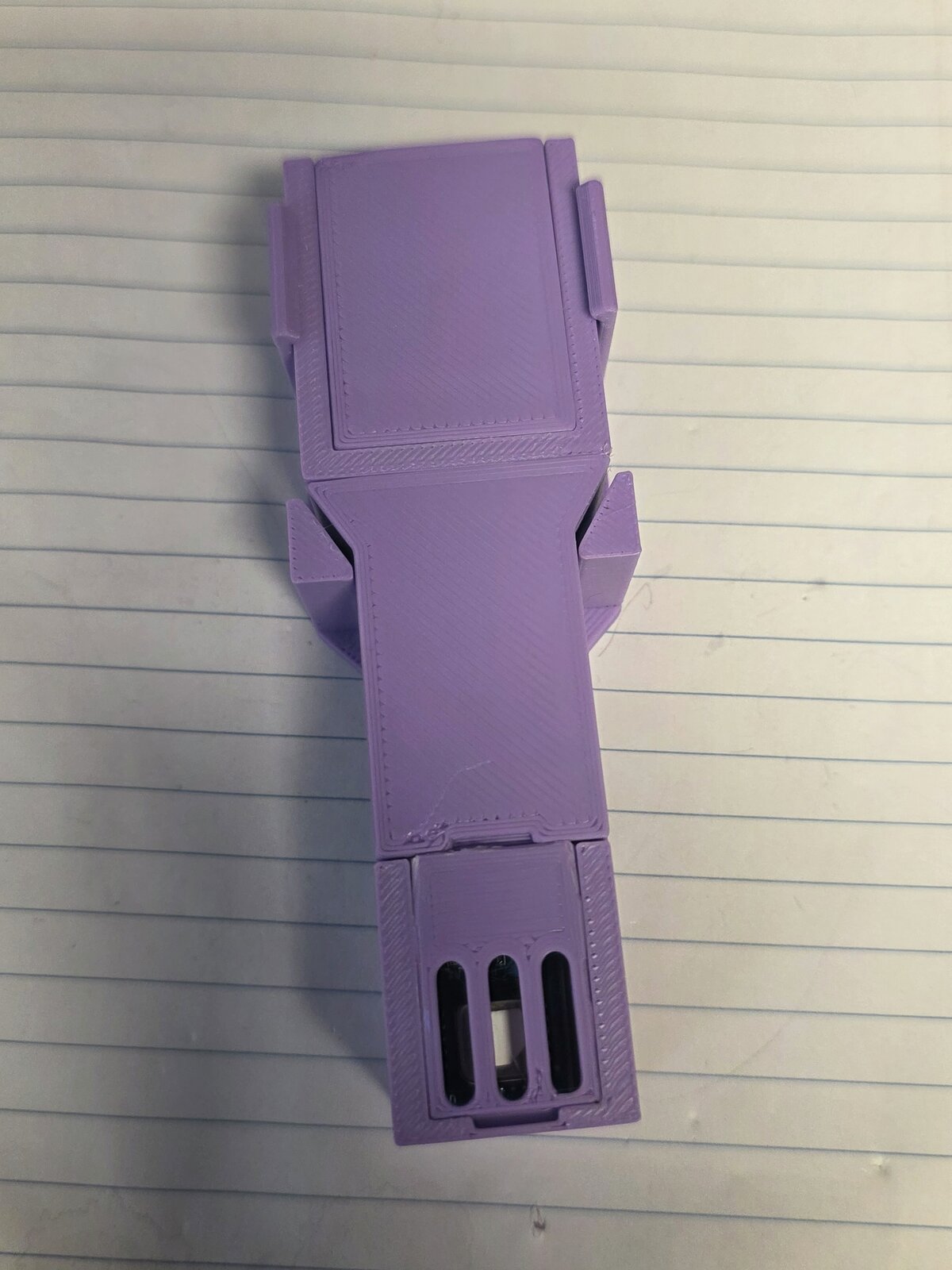
If you want to build one, the OpenSCAD files for the case and the bracket are free to use under CC BY 4.0. Put both in the same folder, since the bracket takes all its measurements from the case file. Measure your boards first, because clones vary, and print the test slices before the full case.
Firmware
The firmware is ESPHome. Here’s the sensor part of the config (Wi-Fi, API and OTA are the usual boilerplate):
esp8266:
  board: d1_mini

i2c:
  sda: GPIO4   # D2
  scl: GPIO5   # D1
  frequency: 100kHz

sensor:
  - platform: scd4x
    id: scd41
    measurement_mode: periodic
    automatic_self_calibration: false
    altitude_compensation: 100m     # set to your own elevation
    update_interval: 60s
    co2:
      name: CO2
    temperature:
      name: Temperature
    humidity:
      name: Humidity

button:
  - platform: template
    name: Calibrate CO2 to 427 ppm
    entity_category: config
    on_press:
      - scd4x.perform_forced_calibration:
          value: 427
          id: scd41
Automatic calibration is off, so the only thing correcting the baseline is the calibrate button. Altitude compensation matters because the sensor is measuring a concentration and air pressure changes with elevation.
First power up
The first flash over USB worked first time. An I2C scan found the sensor at 0x62, which is the SCD4x address.
To check it was really an SCD41 and not an SCD40 sold as one (a common listing trick), I set the first build to measurement_mode: single_shot. That command only exists on the SCD41 - an SCD40 rejects it. It returned readings, so it’s the real thing. After that I switched it to periodic mode over OTA, which is how it runs normally, and the mode the datasheet says to calibrate in.
The first readings in the office were 725 ppm, 25.1C and 63.8% humidity.
Then, for fun, I held it up and breathed on it. The next reading jumped from about 700 to about 9000 ppm. That sounds alarming but it’s normal - exhaled breath is around 40,000 ppm. It’s an easy way to make sure it’s actually responding.
Calibrating it
Out of the box, these sensors can be off by a fair bit, and soldering stresses the sensor and shifts the baseline. Since I’ve turned off the automatic calibration, that’s up to me now. It’s easy - grab a battery bank to power it, take it outside, let it settle in fresh air, and tell it what the outdoor CO2 level is. Outdoor background is about 425-430 ppm these days (it was 400 not that long ago, and it keeps going up), so I used 427.
It took about 10 minutes to clear the indoor air out of the sensor:
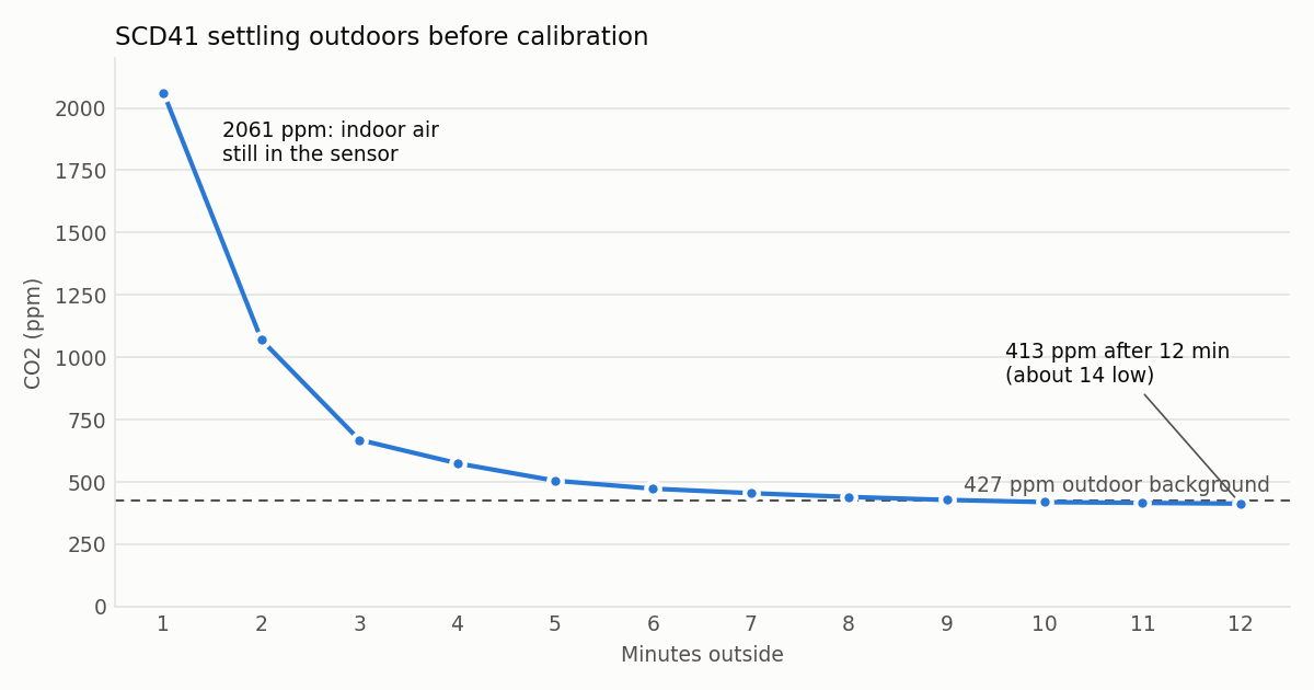
The datasheet says 3 minutes is the minimum. In practice, wait until the readings stop falling. Mine settled at 413-419 ppm, so it was reading about 10 ppm low out of the box, assuming typical outdoor levels. That’s a pretty small, normal offset, and the best I’m going to get without a very expensive professionally calibrated reference to compare it to.
Then I pressed the calibrate button and nothing obvious happened, because I wasn’t watching the device log. There was no way to know if it actually worked. Pressed it again with the log open:
Setting forced calibration Co2 level 427 ppm
Forced calibration complete
The next readings were 439 and 432, settling toward 427. Watch the log when you press the button if you want to be sure it worked.
Two things I wondered about that the datasheet answers:
- Does the calibration survive unplugging it? Yes. ESPHome has a
persist_settingsoption, but that’s only for settings like the temperature offset and altitude. The calibration history is automatically stored in a separate EEPROM on the sensor. - When should you calibrate? No sooner than 5 days after the sensor is soldered in. The soldering stress shifts the baseline and it takes a while to settle. That catches most DIY builds, since everyone (including me) calibrates it the day they build it. So my first calibration is provisional, and I’ll redo it after the 5 days are up.
What’s left
The temperature offset is done. I left my most accurate thermometer about 15 cm from it overnight, in still air with the AC off and nobody in the room, and compared the two between 1 and 6 am. On ESPHome’s default 4C offset it read 1.1C warm, and very steadily (between 0.9 and 1.2C the whole time). So the offset went up to 5.1C, and after the update it read 24.64C against the thermometer’s 24.70C.
That leaves the second calibration, once the 5 days are up on October 6th. Sensirion’s sanity check for a finished build is temperature within 0.5C of a reference, CO2 noise under 20 ppm between readings, and a response to breath in under 60 seconds. It already passes the temperature and breath checks now, so the next check is just to make sure the soldering stress didn’t affect anything.