ChillSaver - A Fridge and Freezer Temperature Alarm
I’ve got a fridge, the freezer on top of it, and a chest freezer beside them. That’s a lot of food, and sometimes even medications that need refrigeration. Power failures, a bad fan or compressor, or even just someone not closing the door tightly can ruin food or cause food poisoning.
Besides food safety, the data can also be used to help tune the temperature controls to the ideal range, and help with monitoring energy efficiency of the appliance.
There are plenty of options out there for monitoring a fridge or freezer temperature. But none had the exact feature set I wanted, at least not at a reasonable price. Especially if I have to buy 3 of them to monitor each zone. I already had all the parts on hand, so the ChillSaver was born.

Features I wanted
- Three probes: fridge, freezer, chest freezer, all on one device.
- A loud local alarm that doesn’t need the network or Home Assistant for anything.
- Fully local connection to Home Assistant, no reliance on cloud services.
- The alarm should tell me which unit has the problem without having to go look at a screen.
- A dead or unplugged probe must never look like a happy fridge.
- Limits adjustable from Home Assistant, but stored on the device so it can be tuned easily without having to do a firmware update every time.
- Probes that can be swapped without opening the case.
Parts
Almost all of this came out of my parts drawer.
- ESP8266 NodeMCU (LoLin V3)
- 3x waterproof DS18B20 probes
- 4.7k pull-up for the 1-Wire bus
- A passive buzzer salvaged from an old motherboard’s speaker header (11 ohm coil)
- NPN transistor, 1k base resistor, 22 ohm series resistor, 1N4148 diode across the buzzer
- A panel mount push button for mute
- A BMP180 shield for room temperature, because I had one
- 3 RJ45 keystone jacks, some Cat5, and a piece of stripboard
- A 3D printed case
Why wired probes?
The obvious approach is battery powered sensors inside each unit. I didn’t want that for two reasons. Coin cells sag badly at freezer temperatures, and 2.4 GHz trying to get out of a metal box isn’t great either.
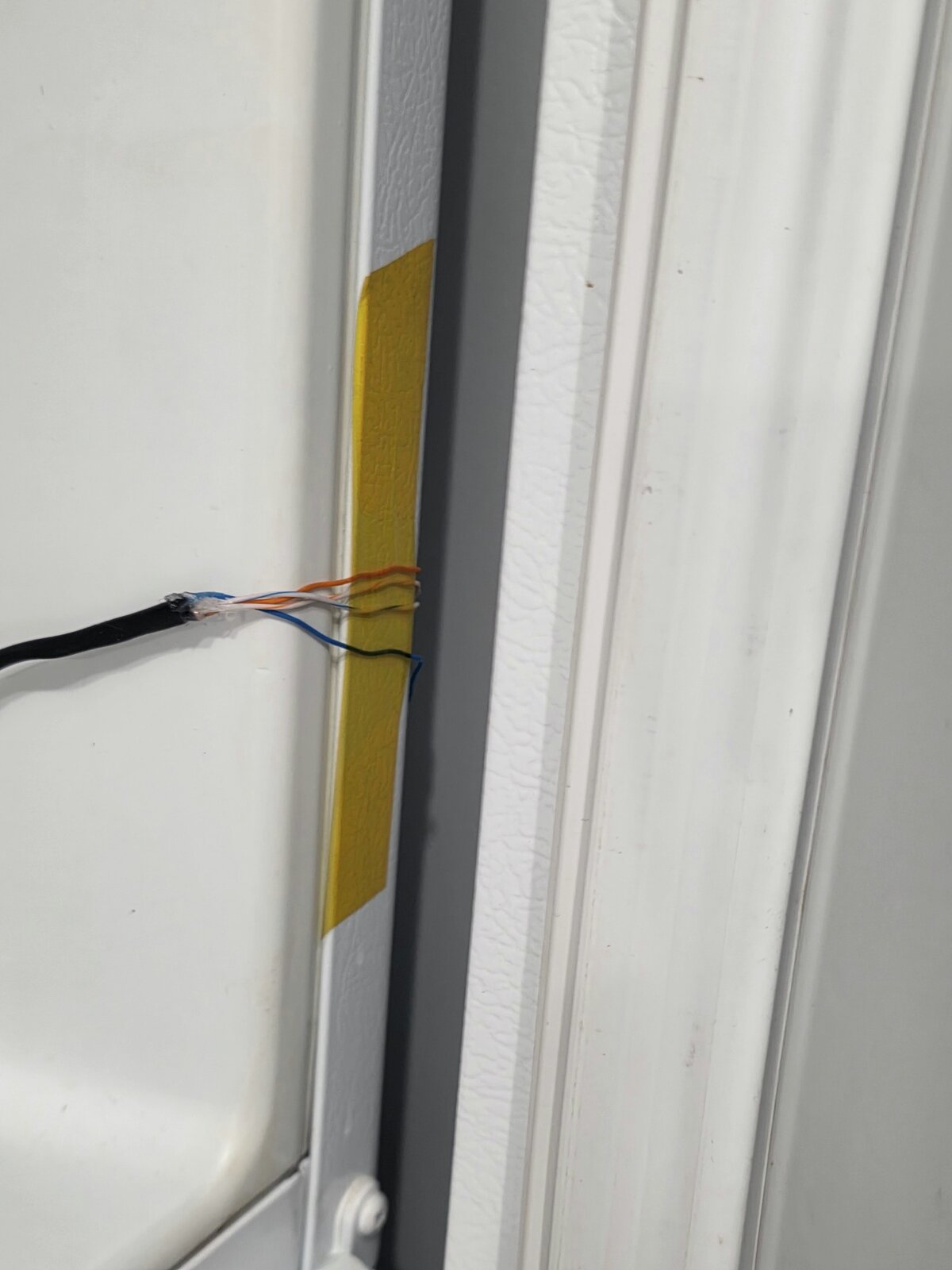
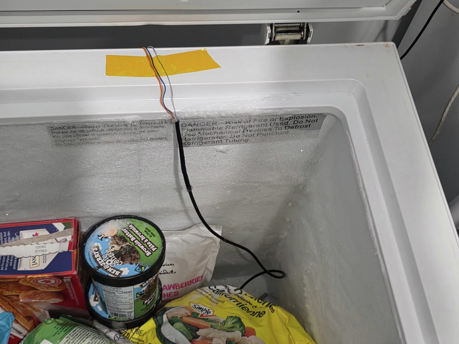
A thin cable through the door gasket on the hinge side shouldn’t leak any noticeable amount. That’s how most commercially available ones work. The DS18B20 probe cable is about 3.75mm though, which is thicker than I wanted squished in a seal, so each probe gets its own run of Cat5 from a keystone jack on the bottom of the case. The Cat5 is joined to the probe cable a few inches inside the unit (soldered, sleeved, hot glue under heat shrink), and the thin flat conductors are what cross the gasket. They get held flat and taped down with thin kapton tape. I put a flashlight in the fridge with the door closed to make sure there was no visible light coming out around the seal.
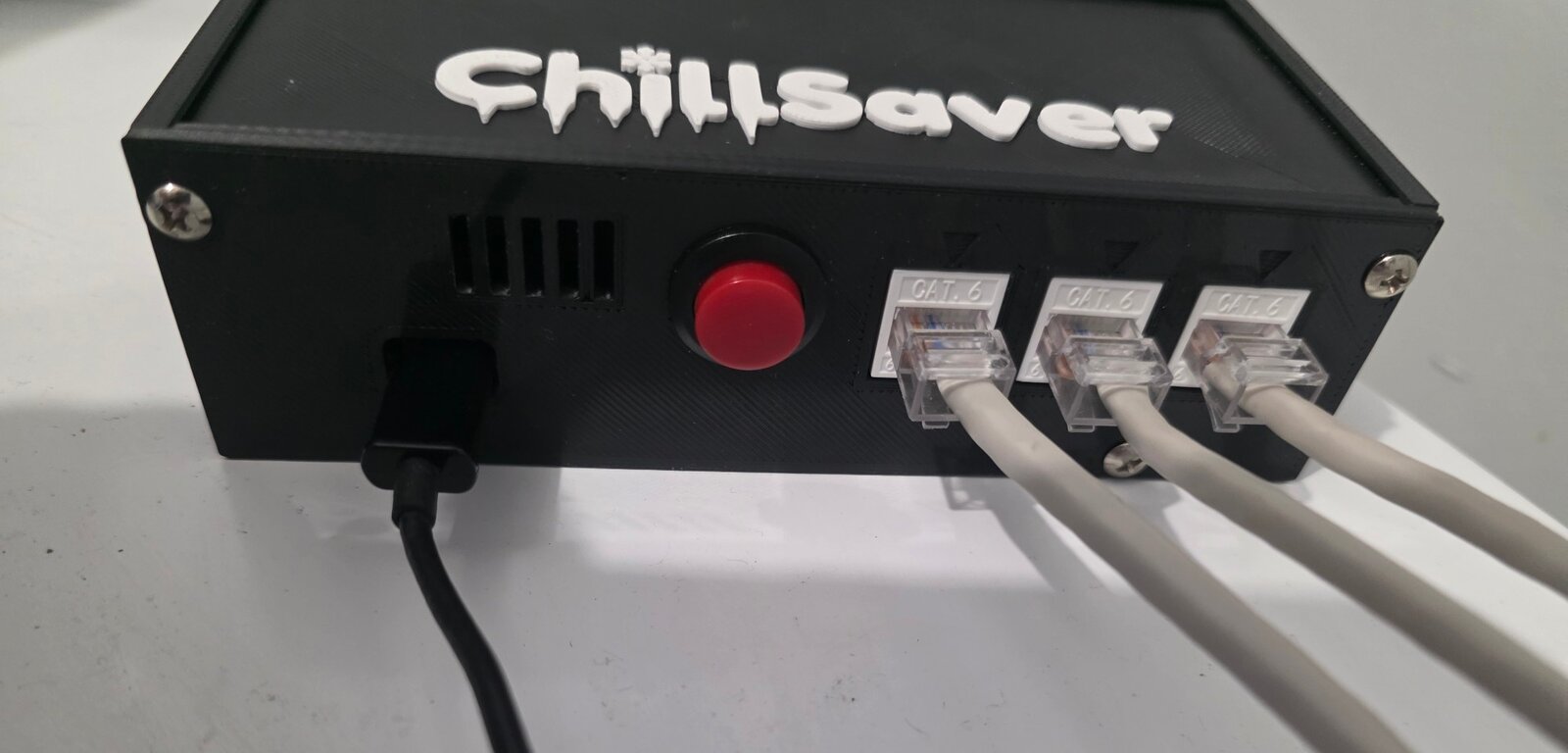
I’ve used Cat5 and keystones like this before and I like it a lot. Ethernet can carry lots of types of signals well, and handle a decent amount of power too. And I’ve always got plenty of ethernet cabling and parts available. A probe can be unplugged and swapped in seconds (not including the time to solder the cable itself up), and every run is wired the same so they’re all interchangeable:
- Pin 4 (blue) is data, pin 5 (white/blue) is ground, so data is twisted with its return
- Pin 2 (orange) is 3.3V, pin 1 (white/orange) is ground
- The rest are unused
The Cat5 I had on hand is solid core. If it cracks from movement in the cold, I’ll redo that run with stranded.

The alarm lives on the device
The firmware is ESPHome. The three probes share one 1-Wire bus, and every 5 seconds the ESP itself checks each one:
- Too warm - a probe has been over its limit for longer than the alarm delay (30 minutes by default). The delay rides out door openings and other short lived temperature swings.
- Probe fault - no valid reading from a probe for 3 minutes. The DS18B20 reports 85C when it powers up without finishing a conversion, and -127C when a read fails, so both of those get thrown out and count as no reading.
The limits, alarm delay and mute duration show up in Home Assistant as number entities, so they’re easy to change, but they’re stored in the ESP’s flash. Home Assistant doesn’t evaluate anything.
The one trap here is that ESPHome, by default, reboots the device if it loses its connection to Home Assistant for 15 minutes. That sounds harmless until you realize a reboot resets the too-warm timer. If Home Assistant is down for a few hours, the device would reboot every 15 minutes and a 30 minute alarm would never fire. So both of those get turned off:
api:
  reboot_timeout: 0s

wifi:
  reboot_timeout: 0s
Making the alarm say which unit
Instead of having to add a display to it, every alarm starts with 1, 2 or 3 short beeps for the fridge, the freezer or the chest freezer. Then:
- Too warm - about 5 seconds of rapid pulsing, repeated back to back until someone deals with it.
- Probe fault - just the beeps, then silence, once a minute. Like a smoke detector with a low battery.
The button mutes it for 2 hours (adjustable), and it re-arms after that if the problem is still there. Holding the button for 2 seconds plays a test alarm.
Getting the sound right took more fiddling than I expected. The buzzer is a passive magnetic one pulled off an old motherboard, driven through a transistor from a PWM pin using ESPHome’s RTTTL player. I added a button in Home Assistant that plays a sweep of six notes, and it turned out the buzzer is only really loud at two of them - B6 and C7, around 2 kHz. Everything else was noticeably quieter.
Then there was what the alarm should sound like. Two tone and warbling patterns sounded musical, not like a problem. The classic smoke alarm triple beep was out too, because that’s what my UPSes sound like, and I’ve learned to ignore those. What I ended up with is C7 pulsed on and off about 7 times a second. It’s obnoxious, which is the point.
Building it
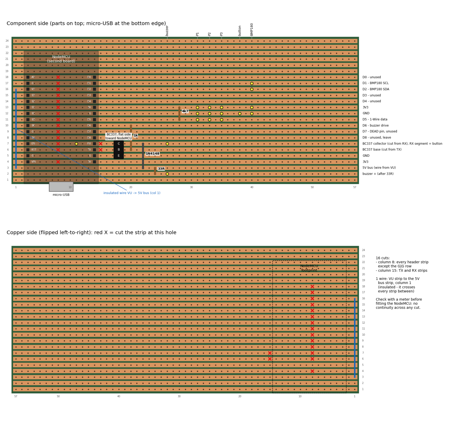
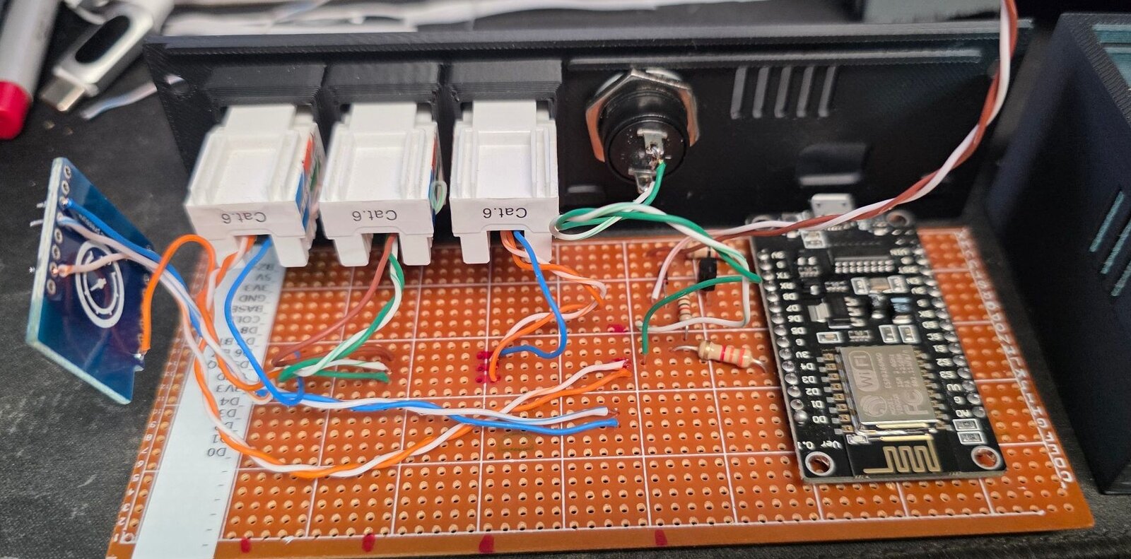
I prototyped it on a breadboard first, then soldered the real one onto stripboard with a second NodeMCU. That’s where most of the fun was.

The first power up looked great. Wi-Fi connected, Home Assistant found it, all the probes were reading. The buzzer was completely silent.
The buzzer’s 5V came from the NodeMCU’s VIN pin, simply because VIN was next to the free strips. It measured 1.2V. On this LoLin board VIN isn’t fed from the micro USB port - it’s only useful when you power the board from an external supply. The breadboard version used the VU pin, which is the USB 5V, and I’d moved it when laying out the stripboard. One cut and one wire to VU later, it was… still silent. Turned out there were two broken wires to the speaker. I fixed the first one and it was still silent. Fixed the second one and it finally made noise.
Then the mute button showed as permanently pressed. The switch, wiring and cuts all tested fine. The pin itself (D7) sat at 0V with nothing connected to it at all. I’m pretty sure it died during the buzzer troubleshooting, perhaps it got shorted to 5v. Rather than replace the NodeMCU, the button moved to the RX pin. That only works if serial logging is turned off, which is fine since the board is soldered down and I use OTA and the network logs anyways:
logger:
  baud_rate: 0
Before installing everything, the probes were put in a dish of ice water to make sure they were all working and returning reasonable numbers. All 3 read within 0.2C of zero after less than a minute.
The case
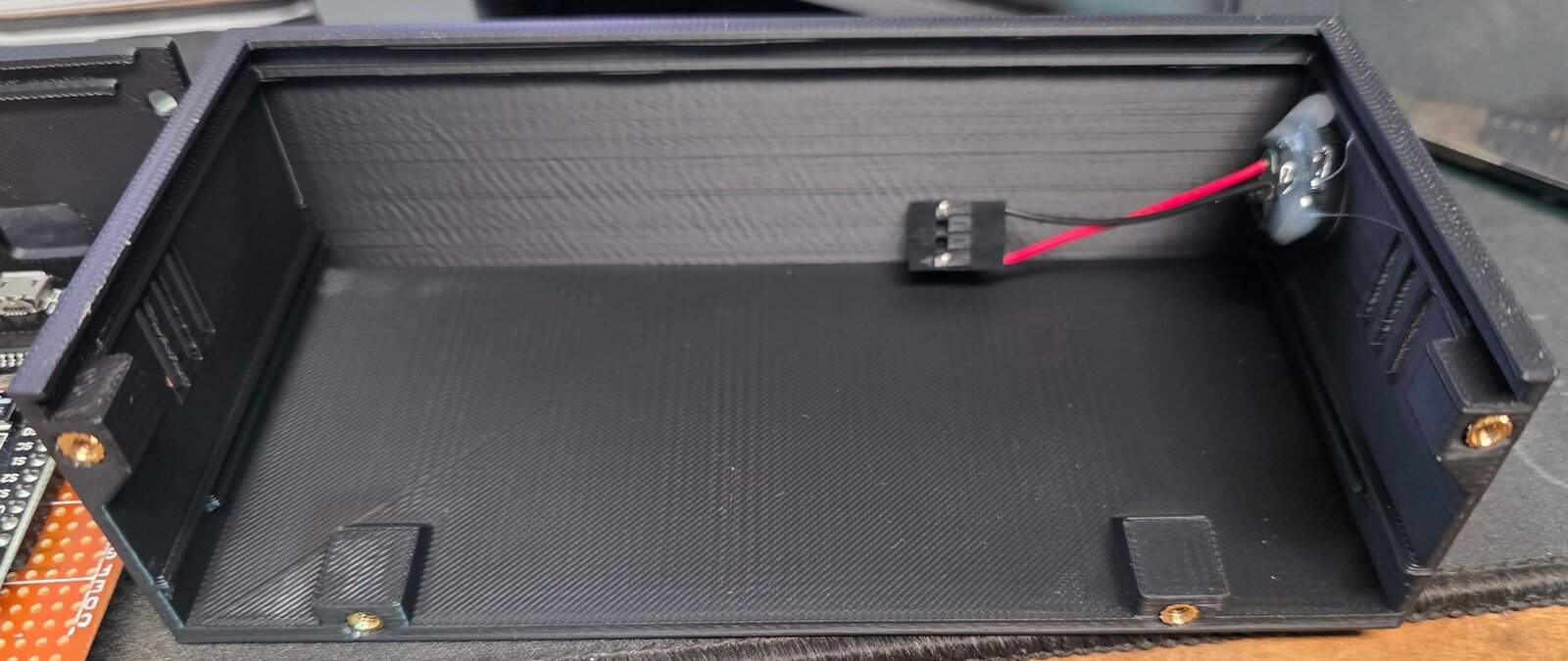
The case was designed in OpenSCAD and printed as three flat pieces. The bottom panel has the micro USB opening, the mute button, the three keystones and some vent slots, so all the cords come out the bottom. The front is just a plate with the ChillSaver logo raised 1mm, printed in one go with a colour change partway up so the letters come out white. The third piece is the back, top and both sides all in one, with rails the stripboard and the front plate slide into, the buzzer glued into a ring behind sound holes in the right side, magnet pockets in the back, two screw tabs on top in case I ever want it on a wall, and bosses for M3 heat-set inserts.
To put it together, the board stands on the bottom panel, the front drops into its slot, the shell slides down over both, and four screws go up through the bottom into the inserts. Nothing pulls apart to open it, so the wires to the button and jacks don’t need any slack. Since the speaker is attached to the case, the wires from the board are soldered to a pin header so the case half can be unplugged from the board.
It took a few rounds to get there:
- The first keystone test print used plain rectangular openings, and the jacks’ latches had nothing to catch on. I ended up borrowing the keystone socket block from spuder’s open source 10 inch rack OpenSCAD project, which clipped in perfectly on the next try. It made the case about 6mm deeper.
- Then test prints to make sure the USB opening was lined up right.
- It started as two halves, with the front and bottom as one piece, but the tall thin front wobbled on the printer’s moving bed. Splitting it into three flat prints fixed that.
- The front originally slid into a tongue and groove, and the thin lip beside the groove snapped off. Full rails, the same as the board rails, are much stronger.
- The first insert bosses were thin rings that softened and warped under the soldering iron. Solid blocks tied into the walls took the inserts perfectly.
The magnets weren’t quite strong enough to hold it up with three Cat5 cables and a USB cord hanging off it, so it kept slowly sliding down. A couple of small, strong magnets stuck to the fridge just under its bottom edge fixed that. The BMP180 shield was a late addition that the case wasn’t designed for, so it just hangs loose inside. It reads about 3 degrees high from the NodeMCU’s own heat and the sensor itself being not great, so there’s a -3 offset on it. It’s only there for comparison, nothing alarms on it.
Home Assistant on top
Home Assistant is the second layer. It sends a push notification to my phone when any of the Too Warm sensors turn on, repeating every 30 minutes while it’s still warm. A probe fault or the device going offline gets checked hourly. There’s no extra delay on the too warm notification - the device already waited 30 minutes, so when that sensor turns on it means it.
These are driven by polling instead of a loop with delays inside the automation. A running automation dies when Home Assistant restarts, and then the nagging just stops without anyone noticing.
The probe was in the wrong place
Once everything was installed, the fridge read -1.9C. That’s below freezing in the fresh food side of the fridge. The history showed it swinging about 5 degrees every time the compressor cycled. The fridge was fine. The probe was just on the back wall, right where the cooling happens, where things sometimes freeze anyways. It was measuring the coldest spot in the fridge. I moved it so it dangles above the bottom shelf, in the middle of the compartment, and within minutes it read 4.9C.
This also settled something I’d been going back and forth on. The standard advice for this kind of monitoring is a buffered probe: the sensor sitting in a small bottle of glycol, so it responds more like the food does instead of the air. That’s a good idea, but my 30 minute alarm delay does the same job of ignoring short blips. If it was buffered, everything would be smoothed out so we don’t notice the swings - fine for food safety, but less useful for things like detecting if the door was left open in a timely manner, or any more detailed analysis of how efficiently the units are running. Easy to add later if it turns out to be useful.
What I’m doing with the data
This wasn’t only about alarms. I’ve got data from my utility meter, and the house’s always-on baseline load has been creeping up in steps. It looks seasonal. The fridge and the chest freezer are obvious suspects, since they work harder when the house is warm, and neither was being measured. So along with ChillSaver, the fridge got a Zigbee smart plug that meters power. It’s locked in metering-only mode so nothing - an automation, a voice command, or someone poking the button - can ever turn the fridge off.
One night of data already turned up a few things:
- The fridge (a top freezer model) draws about 105W with the compressor running. Left alone overnight it ran about 27% of the time, averaging about 29W. That’s right in line with its Energy Star rating.
- It caught a defrost cycle: about 430W for 12 minutes, followed by a 2.5 hour compressor run to recover.
- The compressor kicks in when the fridge probe hits about 4.8-4.9C, so the probe and the power line up nicely.
- The light in the fridge is a 40W incandescent bulb. Should probably swap that for an LED just for the heat savings.
- The chest freezer doesn’t have a plug on it yet, but the temperature alone tells a story. It was cycling like clockwork every 31-34 minutes: about 19 minutes cooling and 15 warming, so running about 55% of the time, at -24.6 to -19.4C. The dial was on MAX. It also doesn’t have the 8” of clearance the manual asks for, which doesn’t help.
So the chest freezer dial went from MAX down to 4, and I’ll know if that’s too warm. On the fridge, the freezer slider isn’t really a freezer temperature control - it balances the cold air between the two compartments, and it has to be tuned together with the main temperature dial to get both sides right. I moved it to its coldest setting as a starting point. That’s always been guesswork before, and it’ll be a lot easier now that I can actually see what each compartment is doing.
What’s next
What’s left is mostly fine tuning - after it’s gathered a week or so of data, I’ll have a better idea where to set the limits, and also be able to adjust all the controls to keep them in the right temperature ranges.