DIY Numberpad Mechanical Keyboard
I recently bought a Kinesis Gaming split keyboard. It’s not a cheap keyboard, and probably more than I really need, but I was getting really sick of my old keyboard. The Microsoft Natural Ergonomic 4000 has been my only keyboard for at least the last decade. I really love the layout of it - the split design has saved me from wrist problems, and after a bit of practice it was easy to type on. I’ve been through about 5 of them. There are two downsides to it though. First, you can’t buy them anymore, at least not at any reasonable price. Second, the mushy membrane keys are fustrating. Mine had a few keys that had to be pressed really hard in order for them to register, and it was getting fustrating not having my keystrokes register.
Anyways, the new keyboard is great. Takes some getting used to, but it’s working well for me. I’m starting to get used to having the halves of the keyboard spread apart more so my arms are more comforatble. But what it really lacks is a numberpad. Most of the time I don’t need it, but when I do it’s really annoying to not have it. It also doesn’t have any easily accessible media keys - they are there, but you have to hit Fn, and I don’t have time for that!
So I built myself a mechanical numberpad with a few extra keys. I could have just bought one, but where’s the fun in that?
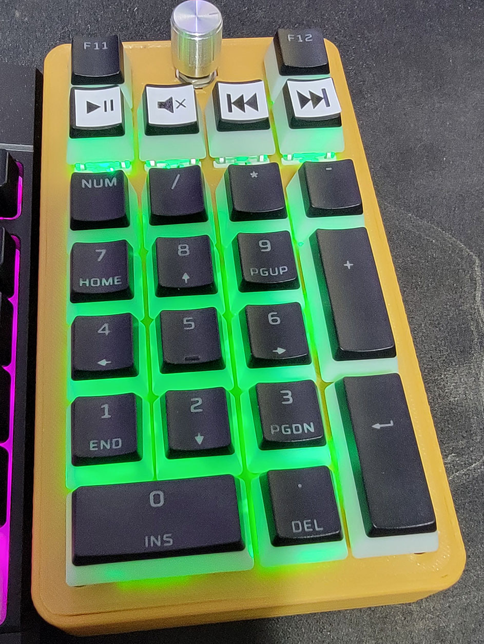
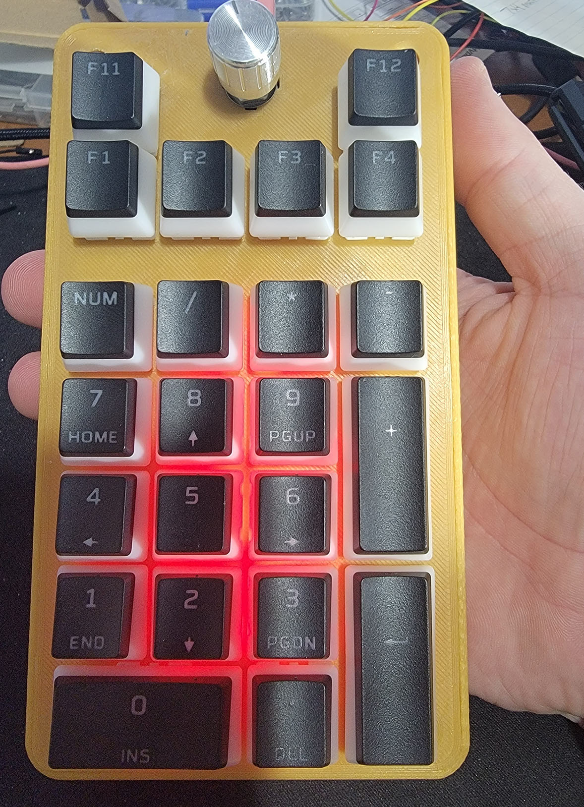
Finished Product
Features I wanted
- 3D printable
- Some way to adjust the height and tilt easily
- Multimedia keys and a volume knob
- Make sure it’s easy to replace the microcontroller without rewiring everything, for when I break the connector off
Step 1: Gather the parts
Most of these came from aliexpress and amazon. Some I had lying around.
- Cherry MX or compatible keyswitches. At least 23 of them.
- Rotary encoder
- Keycaps
- 1N4148 diodes
- Pro Micro microcontroller
- Right angled pin headers
The keycaps I got from a set of HyperX Pudding keycaps that I replaced some of the keys on the actual keyboard with. I had all the ones for the numberpad left over.
Step 2: Design the keyboard layout
http://www.keyboard-layout-editor.com/ is pretty awesome. Makes it super easy to design a layout, and other tools will import it’s data easily.
The keyboard layout I ended up with is:
[{x:1.5},"Encoder\nF13"],
[{y:-0.5},"F14",{x:2},"F15"],
["Play/\n\n\n\n\n\nPause","Mute","Prev","Next"],
[{y:1.5},"Num Lock","/","*","-"],
["7\nHome","8\n↑","9\nPgUp",{h:2},"+"],
["4\n←","5","6\n→"],
["1\nEnd","2\n↓","3\nPgDn",{h:2},"Enter"],
[{w:2},"0\nIns",".\nDel"]
Wasn’t sure the exact use for each button at this point, but the F13, F14 and F15 buttons can be used as hotkeys in some programs, including AutoHotKey to automate just about anything I want. My earliest version didn’t include the F14 and F15 buttons, but there was room for them on the keypad and in the keyboard matrix without adding much extra wiring, so may as well add them.
Step 3: Get a plate designed
I intend to design the overall case in Fusion 360, but manually layout out each button would be a lot of extra work. https://kbplate.ai03.com/ takes your keyboard layout and creates a DXF file. That can be used for laser cutting or milling, or in my case imported as a sketch in fusion to use as a starting point.
Step 4: Design a case
I imported my DXF file and started designing the top plate. Replaced the switch cutout at the top with one appropriate for a rotary encoder. Opted not to use stabalizers simply because I couldn’t find anywhere reasonably priced to buy them. I extruded the plate 1.5mm which is a good depth to clip the switches in place. Then I made a second sketch with a 1.75mm offset around each switch and extruded what was left by another 4.5mm. This leaves clearance around the switches, but makes the top plate a lot more sturdy so the whole thing flexes less.
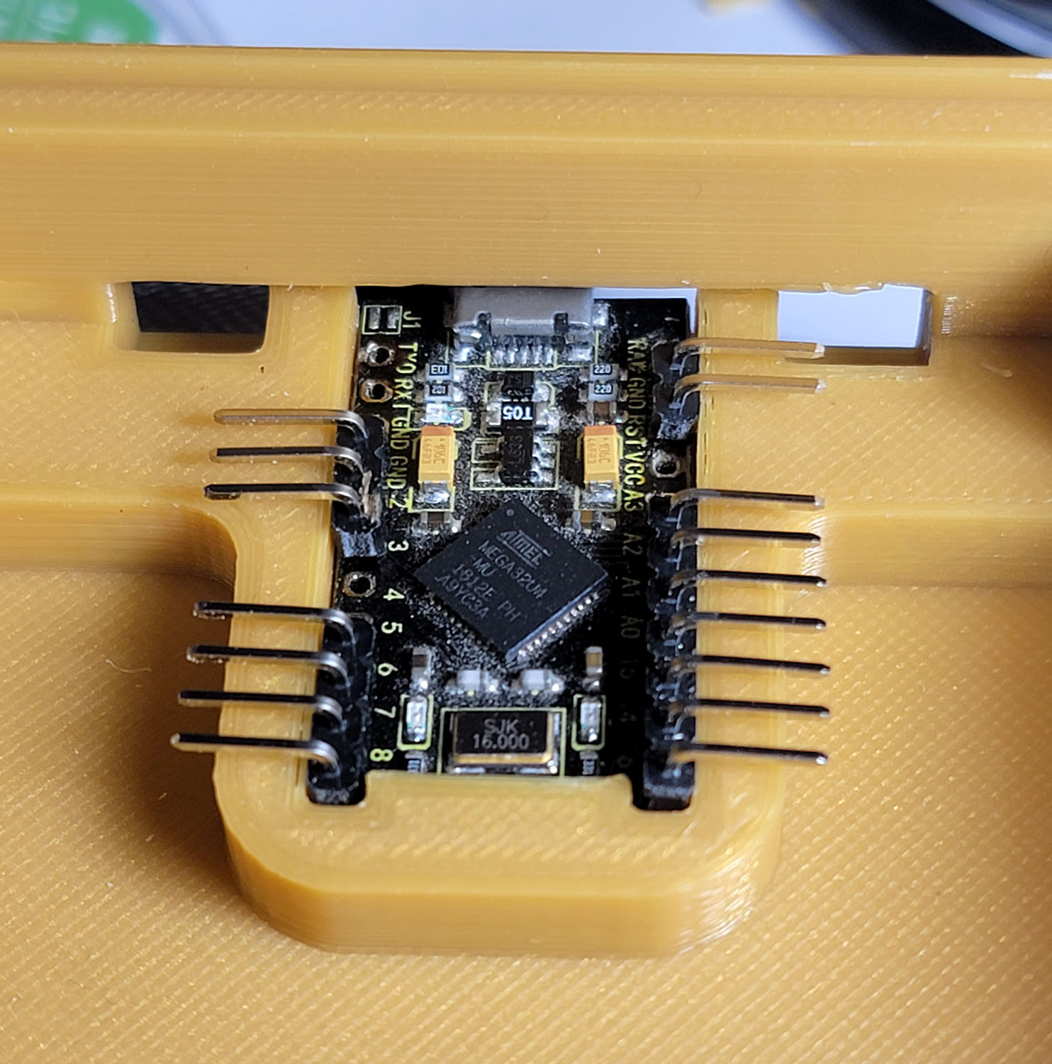
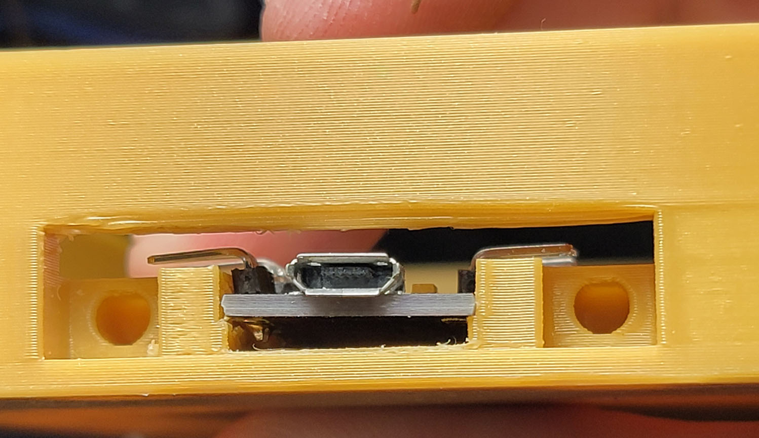
The rest I mostly muddled my way through designing. The top plate sits inside a body that has room for the wiring and microcontroller. Probably more room than I need, but I don’t need this to be super thin. It will get screwed in place with 4 M3 bolts into heat pressed inserts in the body. The body has a mounting area for the microcontroller, designed to let me slide the controller in from the top side with the pin headers already attached, then a cover will screw in there holding the microcontroller in place and covering everything except the USB port. The cover will give me the option of moving to a pro micro with a USB C connector later on, and also makes it easy to get the connector lined up perfectly since it only takes a 10 minute print to make a new cover instead of a 7 hour print for a new frame.
There are holes inside posts at each corner that run all the way through the frame for the screws for the top plate. Having the holes go all the way through lets me not have to worry as much about screw length, and will also let me put a second set of threaded inserts in the bottom. These will be used to screw in legs that let me adjust the height and tilt of the keyboard without having to reprint the entire frame.
The main thing I keep in mind when trying to design parts like this is how I am going to print it. If you know what orientation you are going to print each part, it’s easier to ensure you don’t have any unnecessary overhangs or other difficult to print features. In some places they are unavoidable, but I try to make them on less critical dimensions. For example the hole where the cover for the microcontroller goes will require supports. The holes that it screws into however won’t - even if it doesn’t print a perfect hole with the overhangs there, I’m heat pressing an insert into it anyways so I don’t have to worry about the holes being perfect.
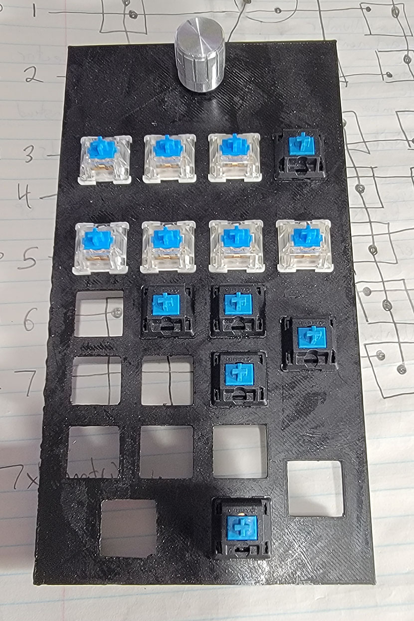
The design took a few iterations to figure out exactly what I wanted and whether or not everything would work. The first print was just the top plate to make sure the spacing and fit was good and there was sufficient clearance around the rotary encoder for the knobs I had. After testing that one I decided to add the additional 2 buttons to the side of the encoder.
The second test print was the frame, but with just a cutout of where the microcontroller would screw in so I could test fit it and make sure the supports that were needed there wouldn’t be hard to remove. This too took a few iterations to find a way to hold the board securely in place without interfering with any components or pin headers. It’s still not quite as secure as I’d like, but it should be good enough that it won’t get pushed out of place while plugging it in.
Step 5: Plan the wiring
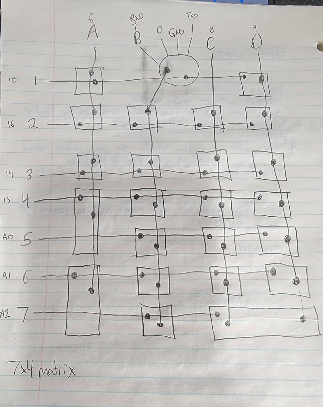
This I find easiest to do on paper. Draw out the layout of the keyboard upside down, so you’re looking at the bottom of the top plate. That makes it far easier to follow when you come to actually soldering it up.
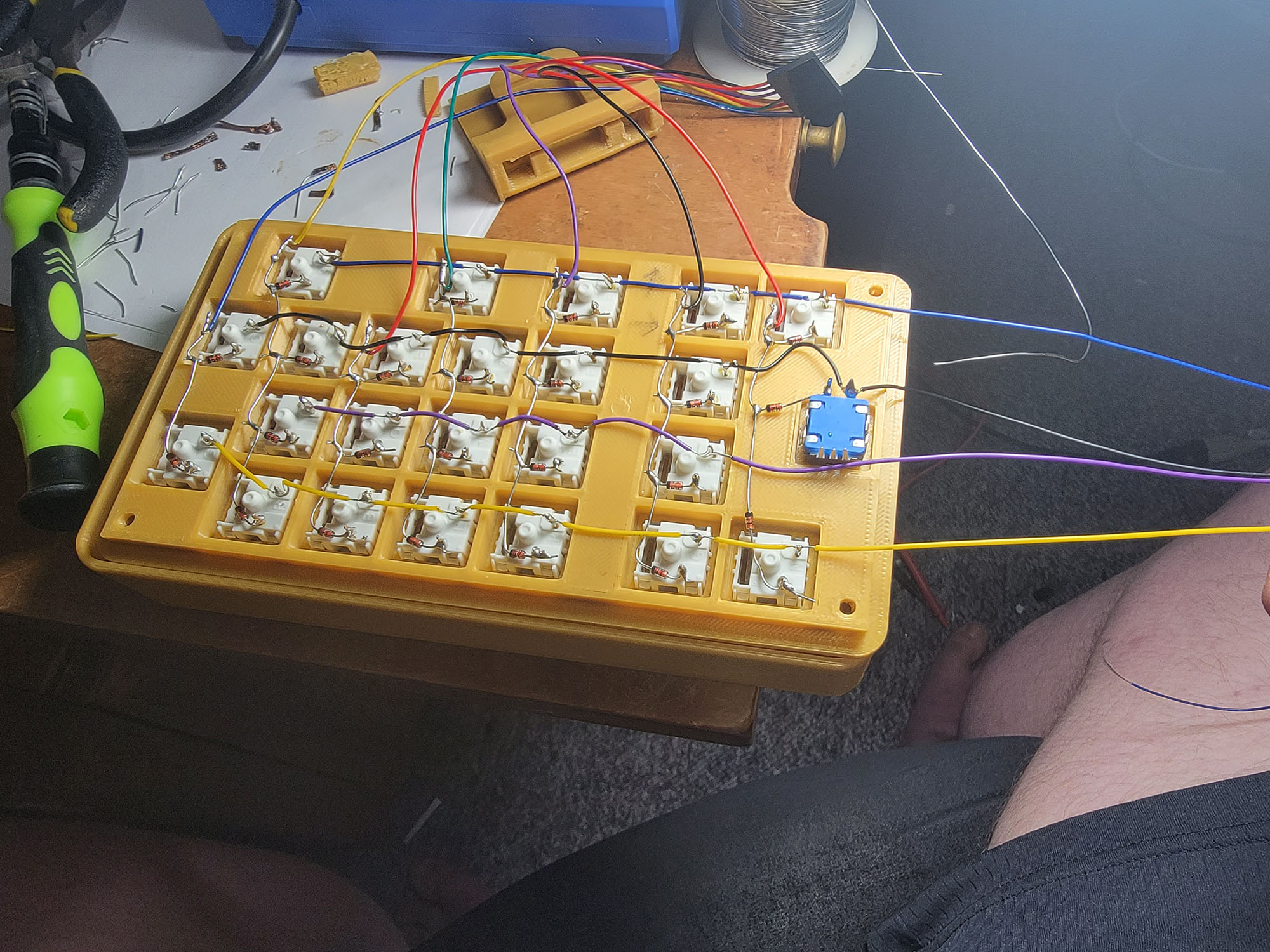
Then figure out the rows and columns, and which switches will connect where. I ended doing a few possible layouts before settling on what would be the easiest to physically wire up. Initially I thought I would use a 5x5 or 6x4 matrix, since both of those give enough spots for the buttons I have, but the layout would have been hard with rows jumping up and down all over the place because of the wider buttons. I ended up with a 7x4 matrix that’s pretty much a perfect grid, so easy to wire up. There are plenty of pins available on the microcontroller for that.
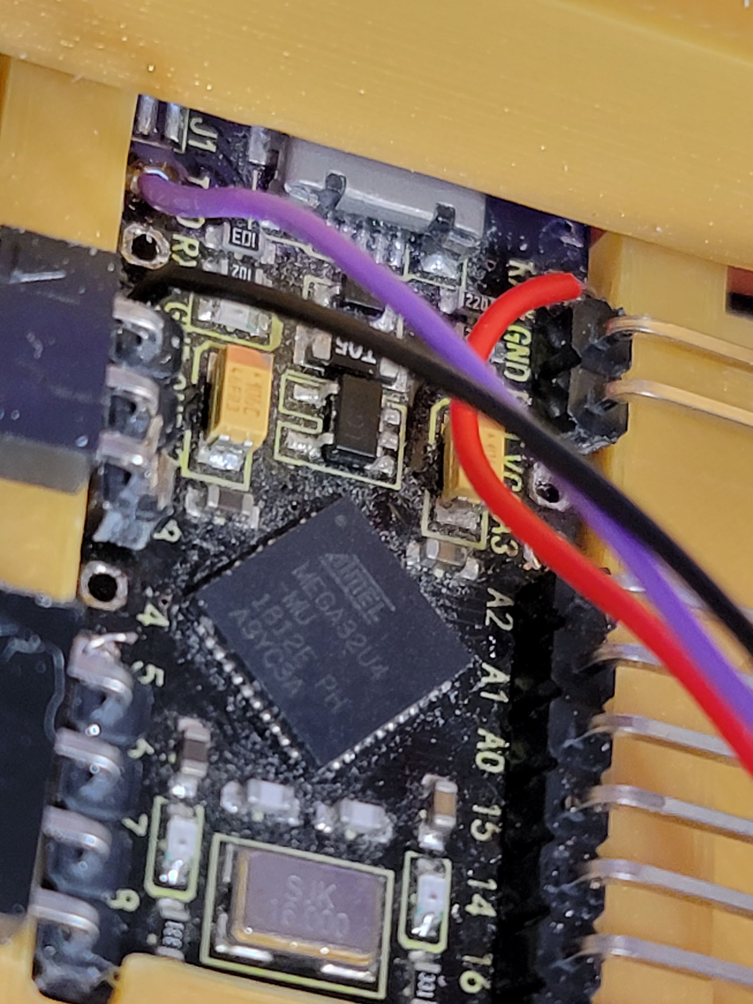
While I’m doing this, I’m also planning which pins I’ll use on the microcontroller to make it easiest to wire. The 3 pins of the encoder were going to go to the TX,RX and ground pins, simply because I needed a ground, and the other two put them all next to each other for an easy 3 pin connector. After test fitting I realized the top pin won’t be accessible, so I moved that down to use the ground, 2 and 3 pins. The columns will use the bottom 4 pins on the left side, and the rows will use the bottom 7 pins on the right side.
Step 6: Firmware
I could jump right into the wiring now, but since I’ve never wired a keyboard with diodes before, I wanted to be able to triple check that I had everything wired correctly. So first I need to get the microcontroller working and firmware installed, then I can test a few buttons on a breadboard and make sure everything is working the way I expect it to.
The firmware I’m using is QMK, simply because it seemed to have an active community and good documentation, and definitely supported the rotary encoder. There’s an online tool for configuring it, but since I like to know exactly how things work on the inside, I went the route of compiling and configuring it from the source code. Their documentation does a great job of walking you through getting the build environment setup.
Download QMK MSYS and install it. Follow along with the prompts.
Then create a custom keyboard with ‘‘qmk new-keyboard’’ and enter a name for your keyboard. I went with grantemsley/numpad. That creates a folder for all your keyboard’s configuration. Find the new keyboard folder and edit some files.
kbfirmware.com is a useful site for taking the output of the keyboard layout generated at the other site and generating the matrix to use and mapping pins and everything, but I opted to go without it so I can learn how the firmware works.
The most important parts are defining what pins are used for the matrix in config.h, and the LAYOUT macro in numpad.h - this layout file defines both how the keys are physically laid out, and their position in the matrix. Then edit the keymap file to assign keys to each button. I setup the encoder as volume up and down, and clicking it to be F13. I use AudioSwitch to switch between my headset and speakers when I press F13, so clicking the volume knob changes devices. The other extra keys I assigned as media keys and F14 and F15, which can be used as hotkeys in other programs or AutoHotKey scripts.
Once the firmware was flashed, I tested it by using a wire to connect between each row and column one at a time. While doing this I found none of the keys in the bottom row worked. I had desoldered and resoldered pins on this microcontroller a few times, and the pad that pin connected to probably got lifted up at some point. Repairing that would mean removing that entire section of pin headers, and risk pulling up even more pads, so instead I soldered a jumper wire from that to another unused pin and changed the pin mapping in config.h.
I uploaded the customized firmware to a github repository so I don’t lose it.
There’s still more work to do with the firmware, but I did enough to get it functional for now. One of the most important features is a way to put the controller into programming mode without having to disassemble the case again. Normally you have to short RST to ground, but that pin won’t be accessible without opening it up again. Luckily QMK has that built in, a feature called bootmagic lite. In config.h I defined the row and column of the key I want to use - in this case, the numlock key. Holding numlock while connecting the USB will put it into programming mode for a few seconds so you can flash new firmware without opening it.
Step 7: Wiring
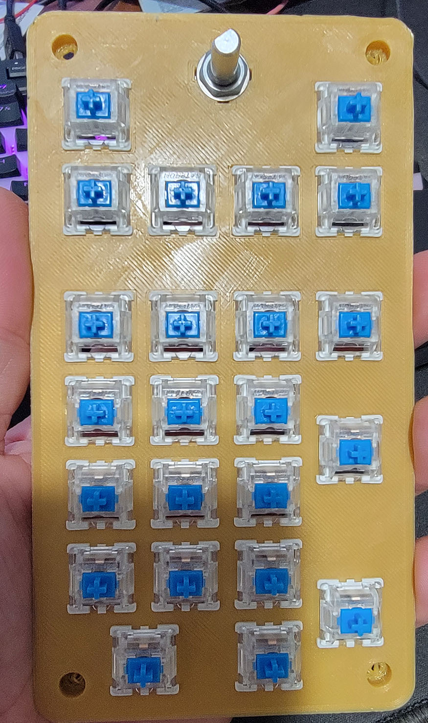
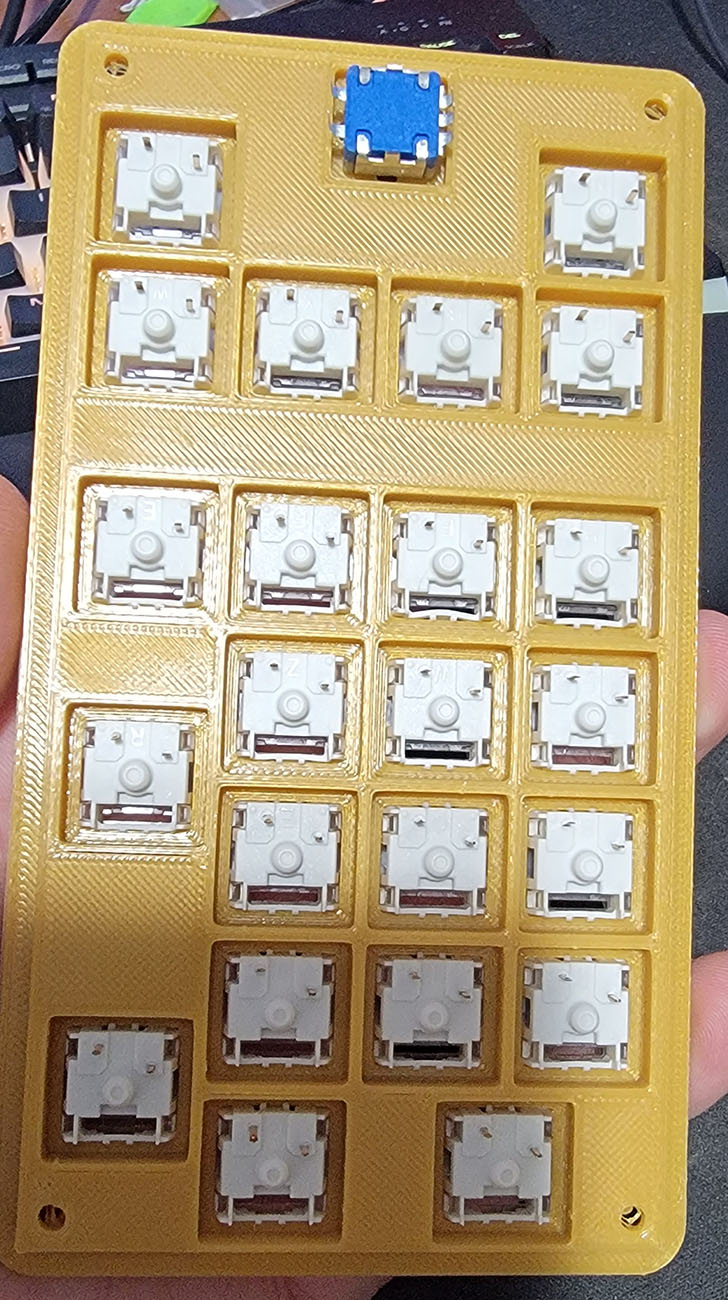
Once the final faceplate was printed, it was time to start assembling and wiring. I installed all the switches with the LED opening on the bottom after reading this: https://keyboardable.com/north-facing-switches-vs-south-facing-switches/. Since I won’t be using LEDs in it, it made no difference to me, and apparently some keycap profiles work better with them in that orientation.
I inserted all the keyswitches and encoder and made sure they all felt like they were working properly. If the opening for the keyswitch is too tight, particularly if you get the thickness of the plate wrong, it can cause the switches to bind up sometimes. Luckily I had figured that out in the earlier test runs where I had made the plate 2mm thick. The 1.5mm thick holes worked perfectly.
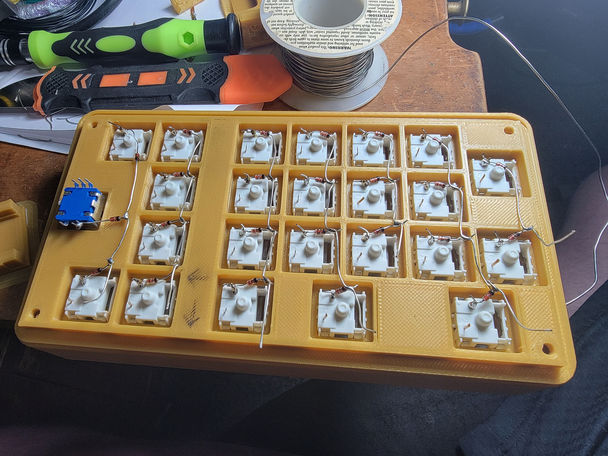
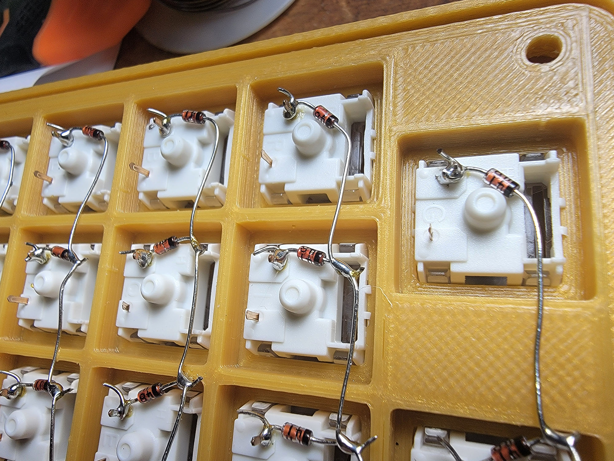
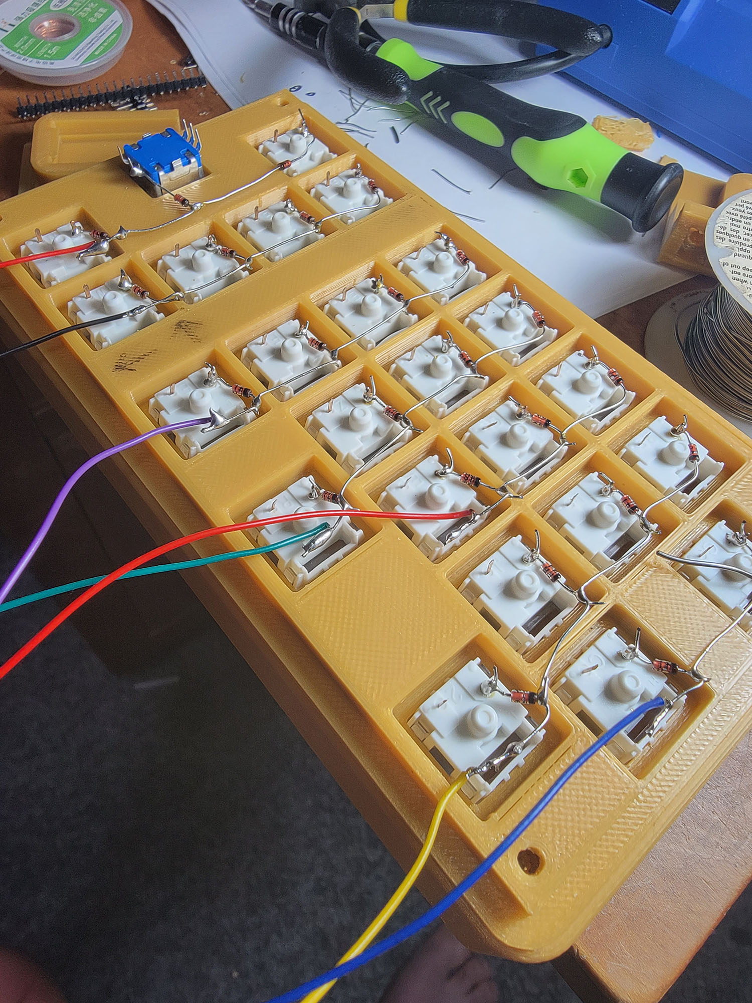
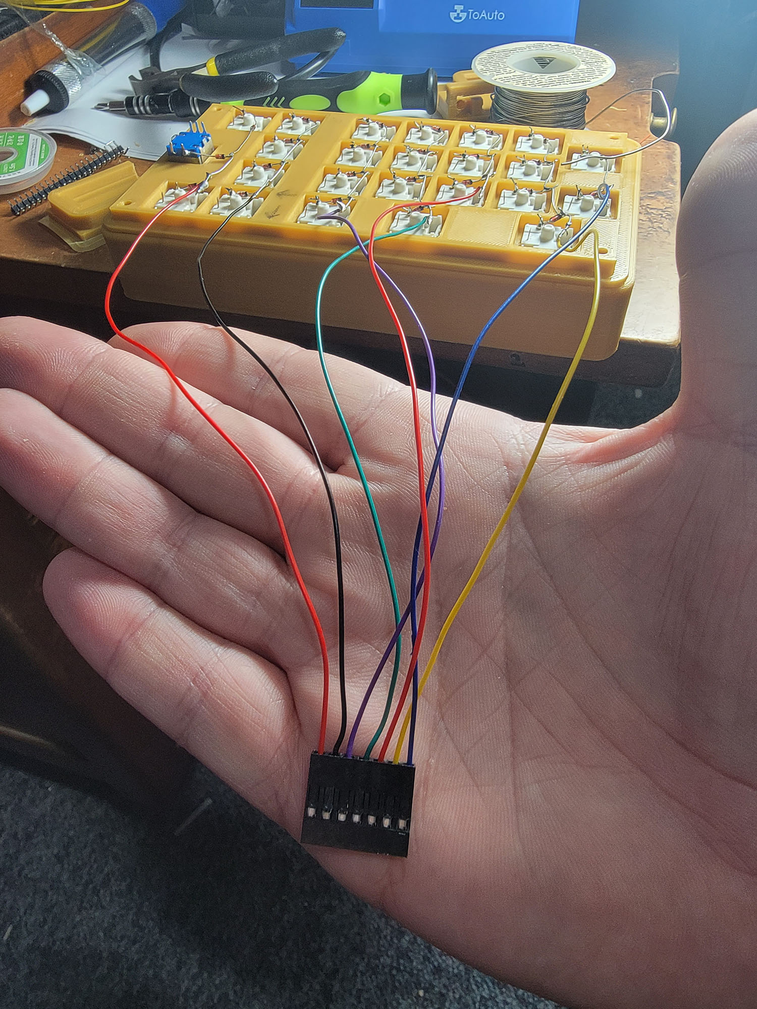
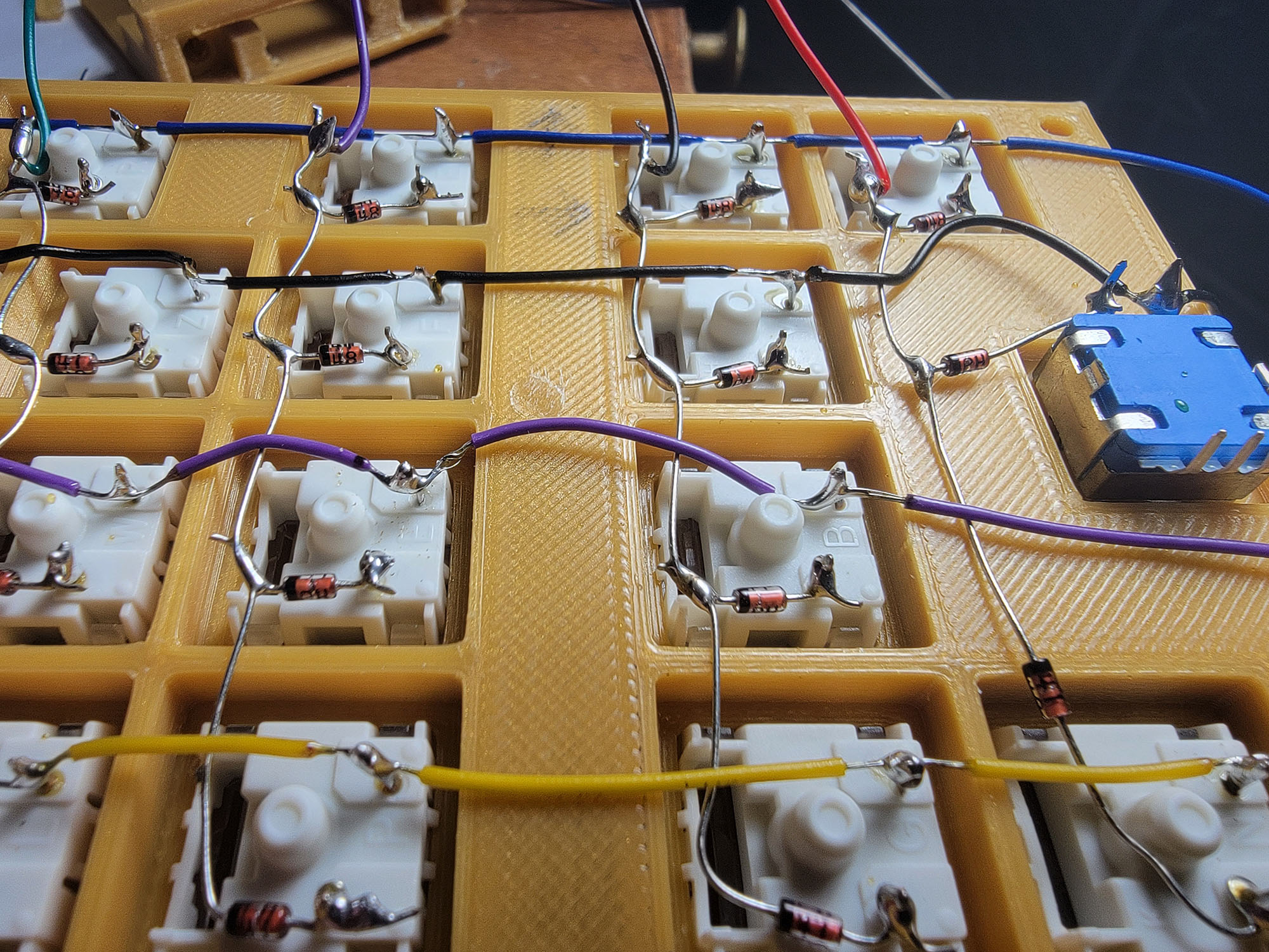
First was soldering the rows. These are made up entirely of diodes and their legs. First bend a tight loop into the leg of the diode away from the black stripe, then put that over the leg and tighten it. Solder that in place. Repeat for each diode in the row. Then starting at one end bend the remaining leg with the black stripe towards the next diode, wrap the leg around the leg of the next one, and solder there. Repeat down to the end of the row, then trim all the legs except for the last one on each row - that’s where you’ll solder the wires for the rows to. I then attached wires to each of the rows and crimped dupont headers to the other end so they can be plugged into the controller.
For the columns, I stripped about 5cm from the end of a wire, then measured how much insulation I’d need between pins. Use the wire strippers to cut the insulation there and push it down the wire leaving a bit of a gap of exposed wire. Then repeat for the next switch. Once I had exposed wire in all the right places, I soldered it down to each switch. It really helps here to tin the wire and the key’s pins before trying to solder them. It took a few tries to get the wires stripped in the right spots, but you can be off by a fair bit without risking any shorts to the row wires. The columns also got crimped to Dupont headers to plug in to the microcontroller.
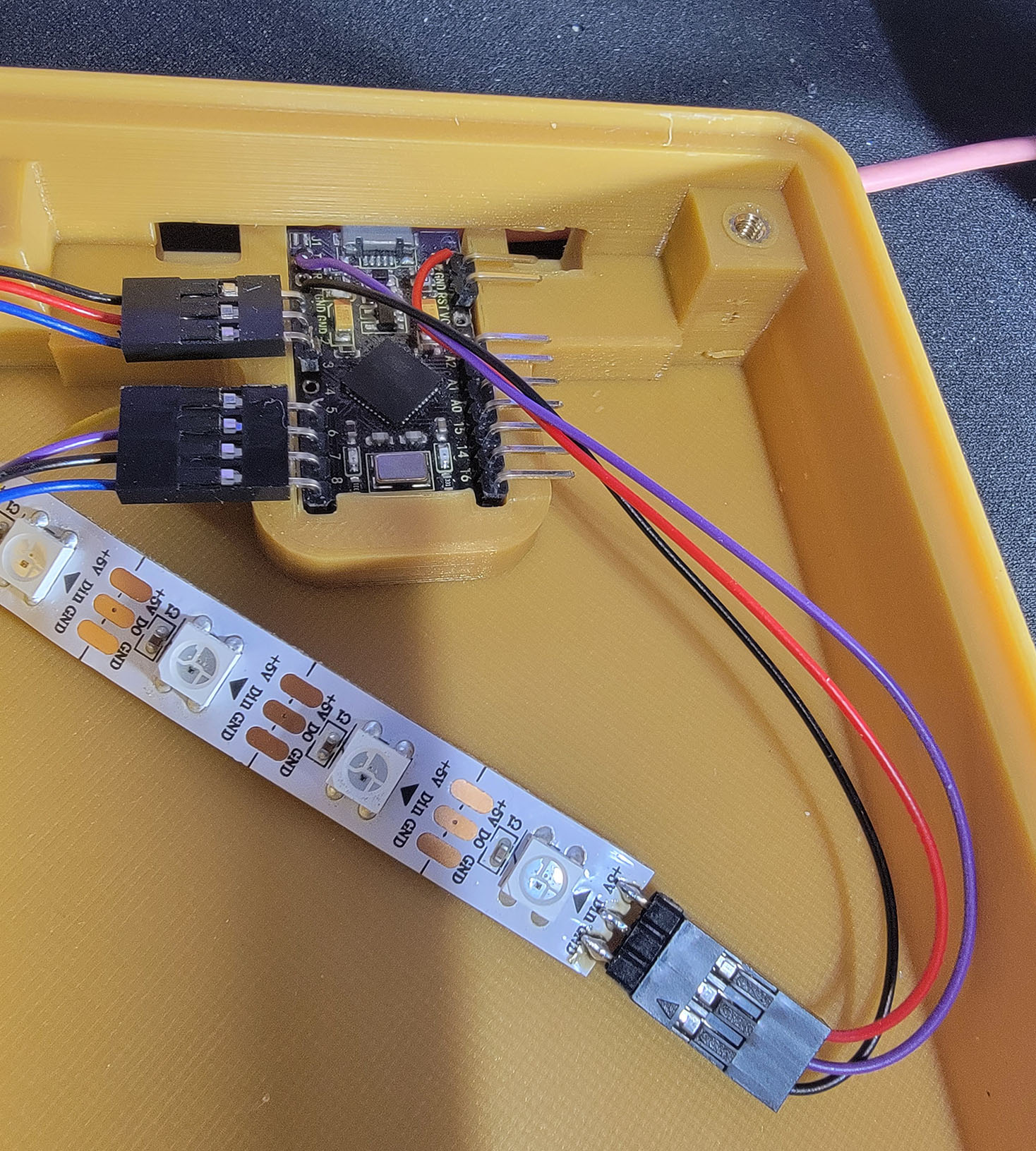
At the last moment I realized I might want to use multiple modes (or layers, as QMK calls them) with this keyboard, and for that I’d want some sort of indication of what mode it’s in. I added another 3 pin header to the RAW, GND and TX pins of the microcontroller and connected a strip of 4 WS2812 LEDs. Because the pins aren’t all together, and those pins are blocked by the case, I didn’t use pin headers in the microcontroller and just soldered the wires to it.

Step 8: Final Assembly
I installed all the threaded inserts and cleaned up the supports around the opening at the back. The microcontroller is held in very securely when the cover is installed, but can be easily removed to swap it out in the future. I’m not happy with how the cover fits, but I’m not unhappy enough to change and reprint it, so it stays.
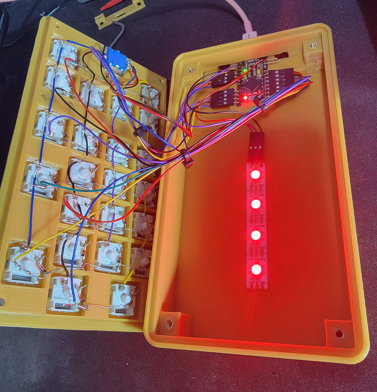
After getting the LEDs to work it looked pretty good. But you know what would look better than 4 LEDs? 20 LEDs! So I opened it up again and added 3 strips of LEDs chained together. The first 6 LEDs run down the center starting at the top, the next 7 are on the left starting at the bottom, then 7 on the right starting at the top. Since that’ll draw a lot of power through the poor little microcontroller, I also set the RGBLIGHT_LIMIT_VAL to 180 instead of 255, to reduce the maximum brightness. Testing with a current meter this made it draw about 420ma with all white lights, and 160ma with all green.
Strangely when I tried it at max brightness, it would draw almost 700ma, and the voltage on the USB port (before the microcontroller) would start dropping to 4.6v. When it did this, it would stay at max brightness for a few seconds, then dim all the LEDs until it was only drawing about 300ma. I kind of expected the controller to just crash, but that doesn’t seem to be the case. Not sure if there is some power limiting code hiding somewhere, or that’s just how it deals with under voltage, but I thought it was odd. No issues with the 180 max brightness, so that’s what I’ll stick to. I’m probably never going to set it to pure white full brightness anyways, so it’ll use less power than that.
Next Steps
There’s still more to do with the firmware. Here are some ideas:
- Figure out how layers work, and use one of the extra keys to switch between layers. Or possibly use the numlock key. Those layers can have other sets of key assignments.
- Use multiple keys at once to set different settings - possibly for switching modes, or for changing the lighting colors.
For now it’s working well enough as intended. I can type numbers at lightning speed again.