RGB Case Lighting
I wanted some RGB case lights. But commercial products only come in two varieties: Expensive, or dumb.
The expensive ones are expensive. And often compatible only with their lights and accessories. And require their proprietary software. The dumb ones have dials for color settings or a few preprogramed options with a remote control, but no computer control of the lights.
I can do better than that.
Inspiration
While looking at the smart controllers, there are the NZXT HUE+ and Corsair RGB Lighting Node Pro. Searching around for comparisons of them, I came across this DIY NZXT HUE+ tutorial by dany_boy on the linustechtips forum.
That got me thinking that I could design my own, similar to that. Of course, it’s not as much fun to just copy what someone else did, so I want to make my own version with my own features.
Hardware Selection
I don’t want to cram a full size arduino into my case, and I don’t have any of the little ones handy. But I did order a couple so called CJMCU ATtiny85 boards from FastTech on a whim - they were the only arduino compatible board that offered a micro USB port instead of the traditional mini. They were super cheap, and I figured I’d find some use for them. What I don’t know yet is if this board is going to be powerful enough to drive the lights - I don’t need many pins, but the board is also very limited on speed and memory. I want to try using the FastLED library, and it says it’s compatible with Trinket boards, which are based on the ATtiny85, so I’m hopeful it will work.
I’ll also need some lights that are compatible with FastLED. The library has good support for most of the common addressable LED strips. Ebay has tons of WS2812B based LED strips available fairly cheap. But I’m impatient so I spent a bit more and ordered these: 5M WS2812B 300 LED. 5 meters is far more than I’ll need.
Environment Setup
First need to setup the development environment. Mostly following this tutorial for setting up the digispark
- Install the arduino IDE and run it
- In preferences, add this to the Additional Boards Manager URLS:
http://digistump.com/package_digistump_index.json - Go to tools, boards, boards manager. Find the
Digistump AVR Boardsand install - It’s supposed to run a driver install afterwards, but doesn’t because arduino doesn’t trust them. It will show an error in the console saying skipping execution of post_install.bat - so you have to go to the folder listed and run it manually. All it does is install the Digispark Bootloader driver.
- Or at least that’s how it’s supposed to work. One of the drivers fails to install for me. So I had to download https://github.com/digistump/DigistumpArduino/releases/download/1.6.7/Digistump.Drivers.zip and run
Install Drivers.exe- for some reason that package worked to install all the drivers. - Set the board type to
Digispark (Default 16.5mhz)
Test out that the board is running with a simple blink sketch. The LED is on pin 1
void setup() {
  pinMode(1, OUTPUT);
}

void loop() {
  digitalWrite(1, HIGH);
  delay(1000);
  digitalWrite(1, LOW);
  delay(1000);
}
Click upload, and plug in the digispark when prompted. You have to leave it unplugged before clicking upload because of how the bootloader works on these boards.
- Now in the arduino IDE, go to Include Library, Manage Libraries, and install the FastLED library.
Wiring LPD8806 LED strip
The WS2812B strip hasn’t come yet, but I do have an old LPD8806 strip lying around with 32 LEDs on it.
I wired the power for the strip to the 5v and GND pins on the board - since this is running off USB power, it’s not going to be able to power all the LEDs, but for testing a little bit this saves me from having to wire up external power. The DI (data in) pin on the strip connects to pin 1, and CI (clock) to pin 2.
Test the strip
I loaded the Blink example from the FastLED library, changed the pin numbers at the top, and uncommented the line FastLED.addLeds<LPD8806, DATA_PIN, CLOCK_PIN, RGB>(leds, NUM_LEDS);
Here’s the code with most of the comments stripped out:
#include "FastLED.h"
#define NUM_LEDS 1
#define DATA_PIN 1
#define CLOCK_PIN 2

// Define the array of leds
CRGB leds[NUM_LEDS];

void setup() {
      FastLED.addLeds<LPD8806, DATA_PIN, CLOCK_PIN, RGB>(leds, NUM_LEDS);
}

void loop() {
  // Turn the LED on, then pause
  leds[0] = CRGB::Red;
  FastLED.show();
  delay(500);
  // Now turn the LED off, then pause
  leds[0] = CRGB::Black;
  FastLED.show();
  delay(500);
}
Upload the sketch, and it blinks the first LED…but green instead of the red the code calls for. I loaded up the RGB calibrate example, changed the pins, and changed the brightness values at the bottom from 255 to 50 to save power. I get 1 green, 2 reds, 3 blues. This means I should define the colors as GRB instead of RGB.
So back to the blink sketch, but use ``FastLED.addLeds<LPD8806, DATA_PIN, CLOCK_PIN, GRB>(leds, NUM_LEDS);`. Blinking is now red.
Now load up the ColorPalette example, change pins and LED type, tell it I have 5 LEDS and upload. Pretty lights!
I want to try it with more LEDs enabled, but first I need to limit the power. Add this line to the setup function:
FastLED.setMaxPowerInVoltsAndMilliamps(5,200);
That will limit the power draw to a very conservative 200ma.
Unfortunately that makes the sketch too big for the microcontroller. That’s going to be a problem. For now, I removed a couple of the demos from the code. It looks pretty.
Well that isn’t going to work…
Unfortunately, the memory limitations on the board aren’t the only problem. It is supposed to support USB, though using virtual bitbanging usb (V-USB). But that alone takes up half the controller’s memory. And it doesn’t work. The included USB examples all result in windows reporting that an unrecognized USB device was connected.
So I can use this to display some preprogrammed effects. Might even be able to squeeze in enough room for a physical button to switch between them. But that leaves me not much better off than a dumb RGB controller. I really wanted to use this due to the tiny size, but it just isn’t going to work out. I might revisit this controller with some of the LEDs I have left over after installing in the case, but for the case I want full control over the LEDs.
Time for plan B.
Plan B
I do have an old Arduino Mega based on the ATmega1280 chip. I bought it back in 2009. An official one, not a clone. This was made before the clones. It’s the first arduino board I ever bought. Over the years it’s been the brains of a remote controlled tank, a monitor for when my clothes dryer stopped, and many other things. But for a long time now, it’s just been sitting all sad and lonely on a shelf somewhere. Guess it’s time for this antique to get back to work.
The Arduino Mega has hardware SPI, a hardware UART for USB serial, 16 times the SRAM and 256 times the flash memory of the ATtiny85. Memory should not be an issue.
It also has the advantage of being able to reprogram it without disconnecting it, which will be nice once it’s installed.
Test the strip on the Arduino Mega
Much like the other controller, 5v and ground are connected to the matching pins on the arduino. DI connects to pin 51 (MOSI), and CI connects to pin 52 (SCK). Change the board type and COM port to match, and upload the code - now it’s using 4% of it’s storage space. Much better.
Power it on and…the LEDs light up randomly and do nothing. Measuring the voltage at the start of the strip shows under 3V. That’s quite the voltage drop. Seems the arduino isn’t liking running it off USB power. So lets connect 12V in to the barrel jack on the arduino and try again. 4.98V at the board, but only 3.01V at the strip.
I’m only using a foot of wire. Also, burning smell. That would be the dust burning off the 5V voltage regulator. It’s not happy with me right now.
Turns out I swapped the data and power pins. Whoops. Oh well, nothing damaged. Put the wires in properly and everything is working.
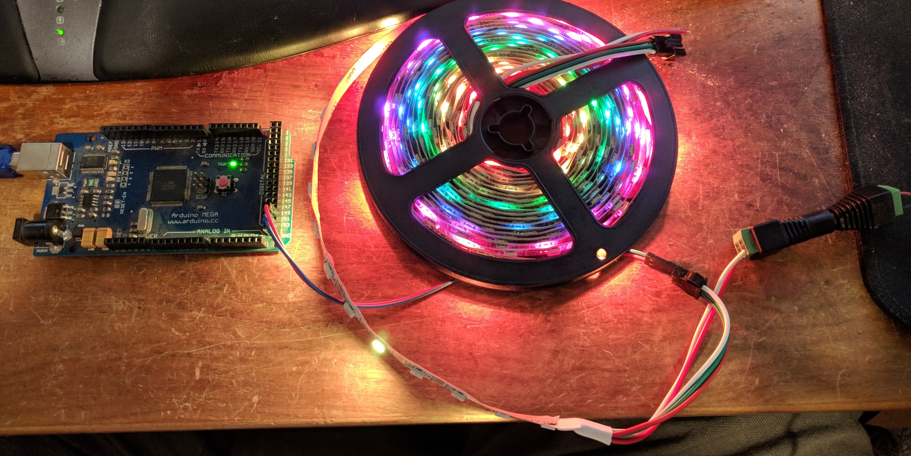
Test the good strip on the Arduino Mega
My spool of 300 LEDs came today. The arduino code requires just changing the FastLED initialization line for the different controllers on this strip. For 300 LEDs, power from USB definitely isn’t going to cut it, so I wired in a 5v AC adapter. The 5v line on the LEDs doesn’t connect to the Arduino at all, only the data and ground pins are connected. The Arduino still gets its power from the USB port.
Lights are looking pretty good on the spool. Effects all work properly. Measured the current draw - 2.5 amps to power the whole strip with rainbow effects. Might be even higher if setting it pure white.
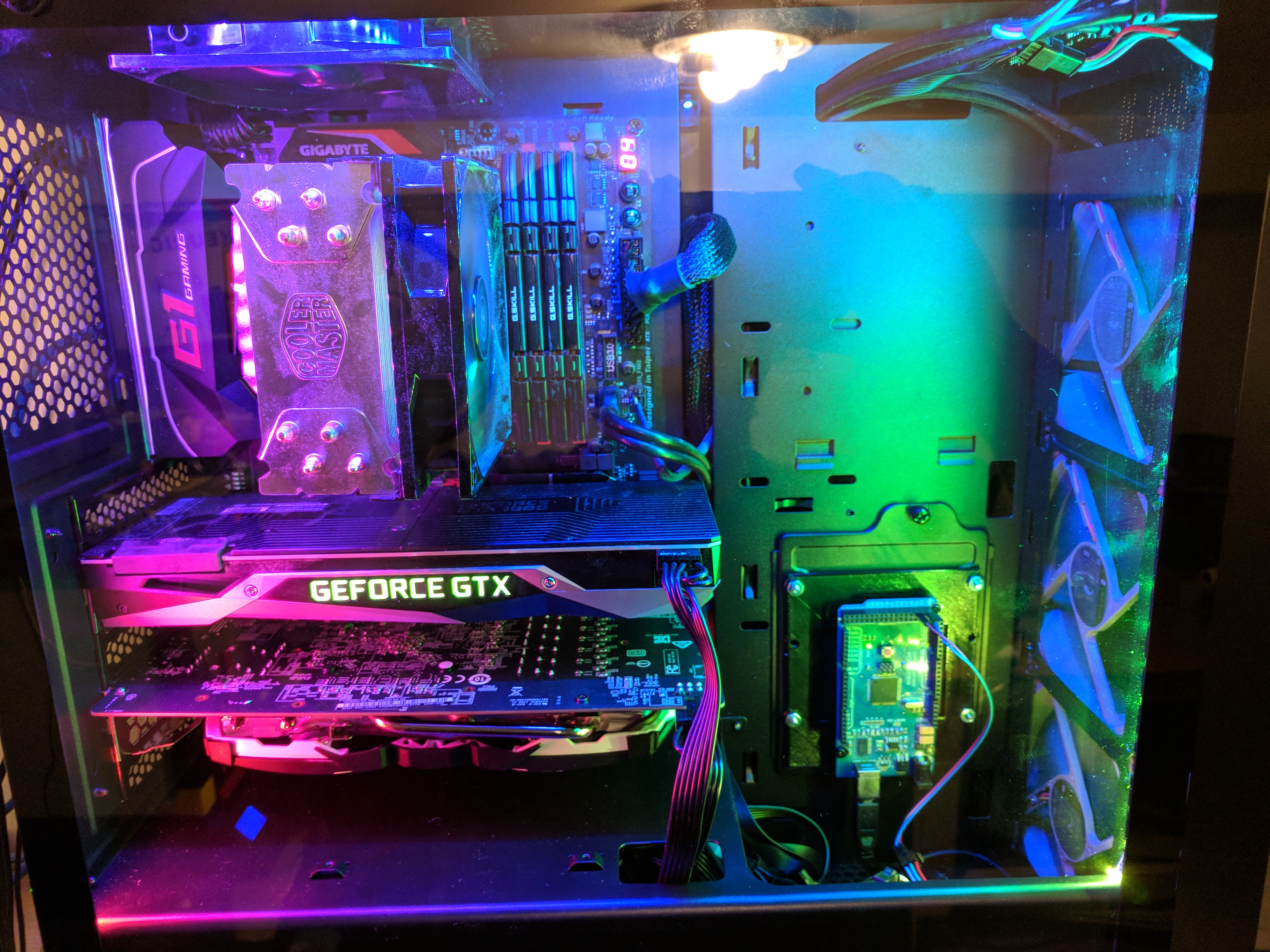
Installation
I’m using a Thermaltake Core G21 tempered glass case. It’s one of the cheapest cases with glass side panels, and looks pretty nice. Installing the lights was pretty simple.
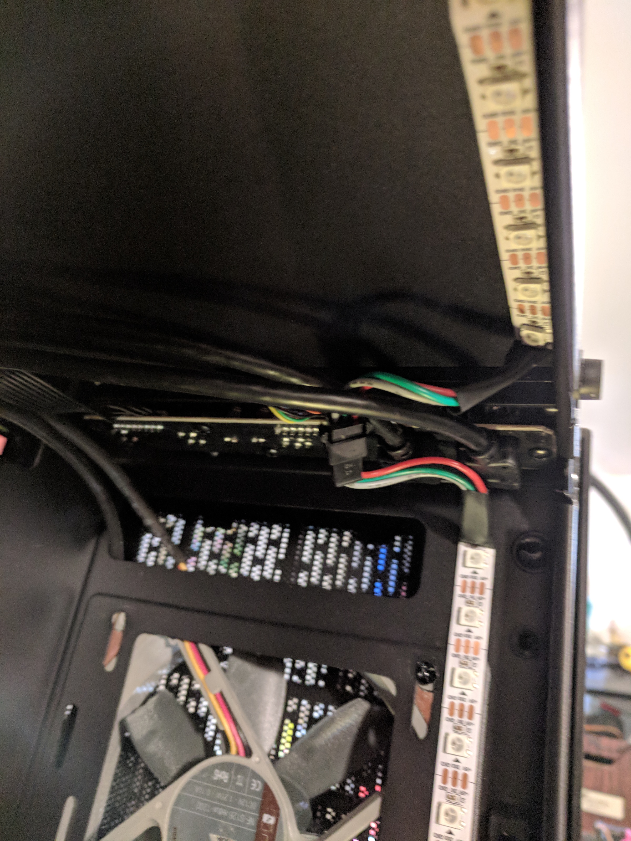
LED Strip
I couldn’t run the strip all the way around the sides and top because the circuit board for the USB ports is in the way. Instead I measured out a strip that goes all the way down the front of the case,
cut the strip there, and soldered a 3 pin JST SM receptacle to the new end. Soldered a JST SM plug to the rest of the strip. Then measured out how much I’d
need to cover the top and back of the case and cut it again. At the front bottom, I crimped a 2 pin JST plug to the power wires that come off the strip, and made 2 pin JST receptacle to molex adapter I made from an fan adapter.
Make sure you use the 5v red wire - 12v will kill the LEDs.
The LEDs just peel and stick to the case. I’m not sure that the tape strips that come on the LEDs are actually strong enough to keep it in place long term, but we’ll see.
I had to remove the rear fan to fit the strip in there. The fan can be put back in afterwards, but might require some longer screws and small washers to raise it away from the LEDs.
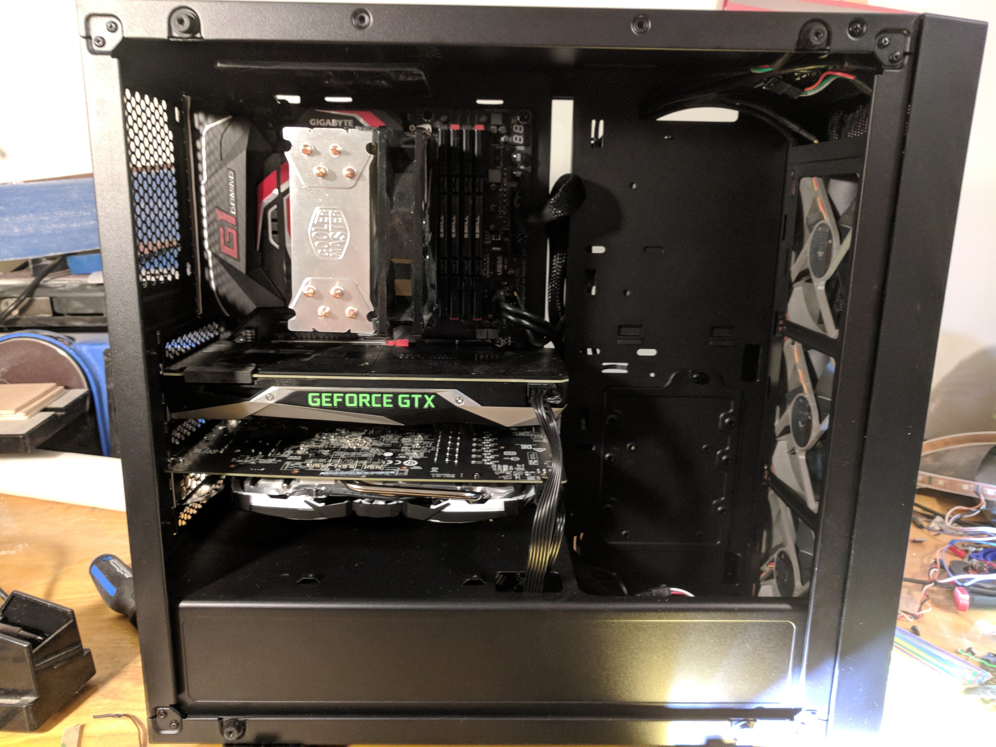
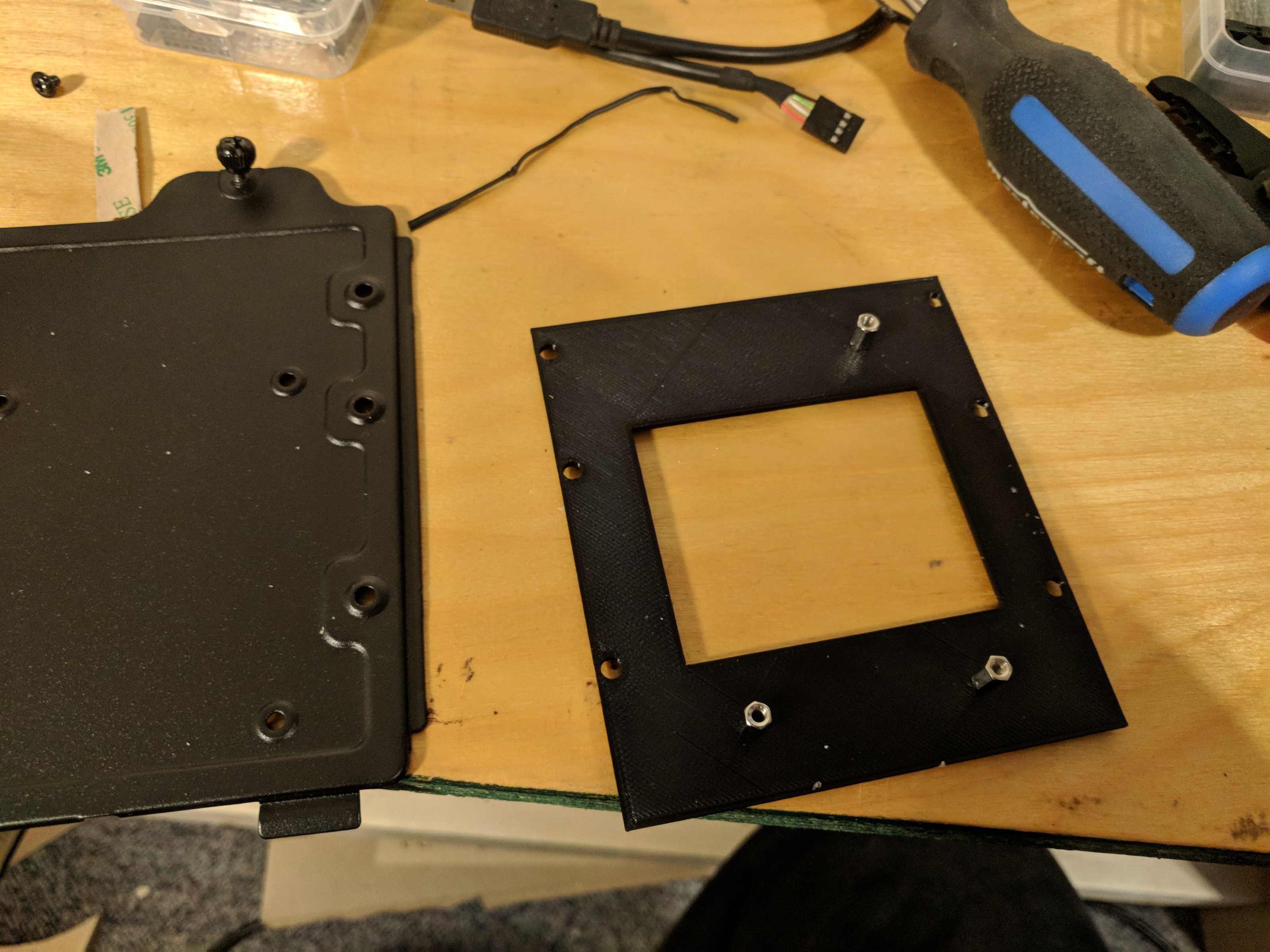
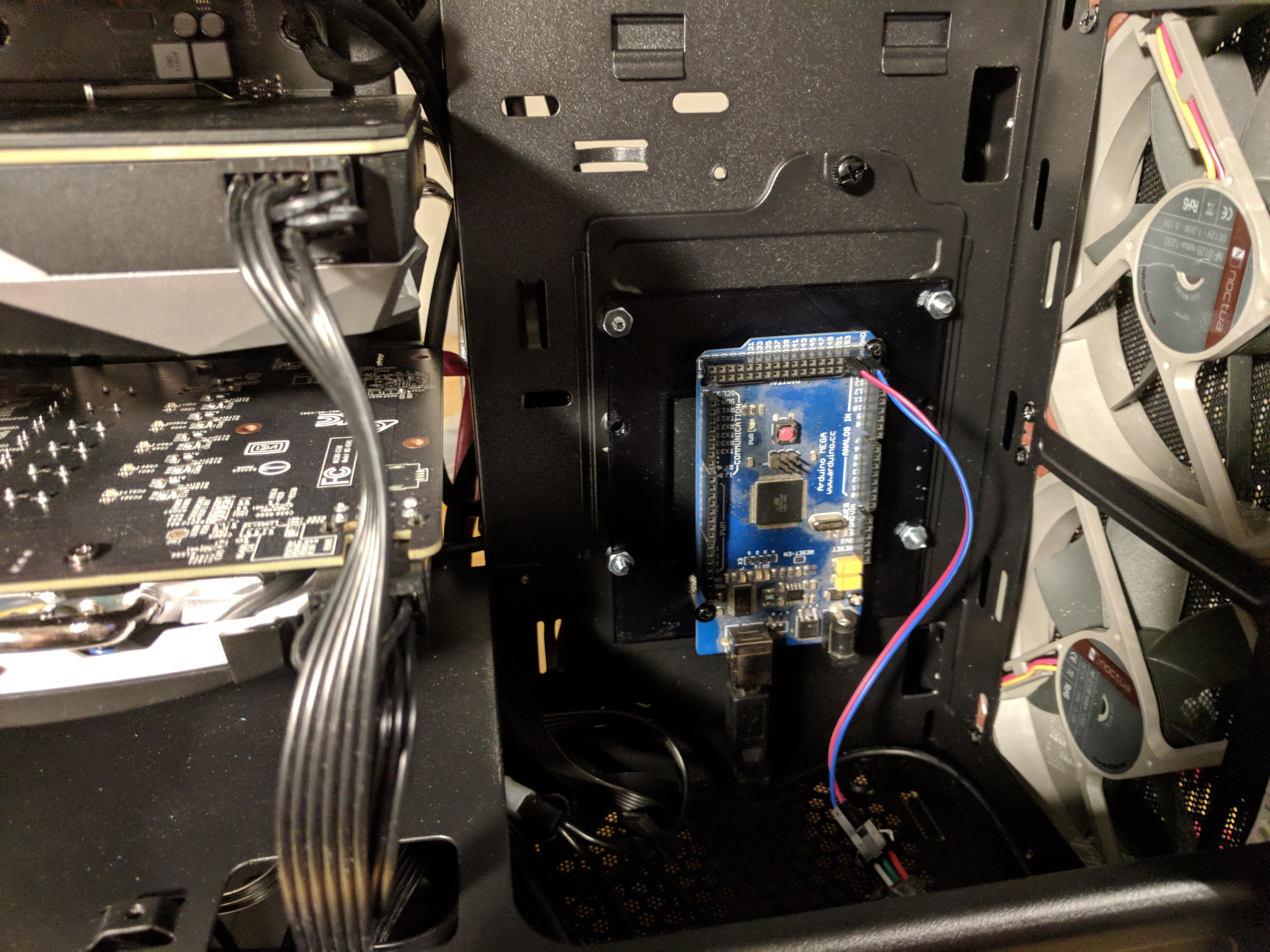
Arduino
I had one hard drive bracket left over after installing my drives in the case, and I wanted to use that to mount the arduino. Normally the drive mounts to the back of the case, but I drilled a new screw hole to let me mount it in the front instead. Then I 3D printed a small bracket that screws into the 3.5” drive mounting holes, and holds standoffs for the Arduino.
A cut up USB cable with pin headers crimped to it connects between the arduino and the motherboard USB header for power and communications with the Arduino
Male to female breadboard wires connect from ground and pin 51 (doesn’t actually matter what pin) to the data connector on the first LED strip.
Software Control
I haven’t actually decided what software I’m going to use to control the LEDs. There are a few that already exist, and I always have the option of writing my own.
One of the best I’ve come across so far is HueHue written by Brian Lima. It’s still a work in progress, but does work pretty well. Unfortunately it’s missing a few features I really want, like changing color scheme when certain programs are running. Which means I either learn some C# .NET programming to contribute to the project, or start writing my own. We’ll see how that goes. But for now it’s looking quite pretty.