MPCNC Machine - Part 1
I’ve always wanted a CNC machine. But they’re expensive, right? Not any more! Check out the V1 Engineering Mostly Printed CNC Machine. Since I already have a 3D printer, I managed to build this thing for under $500 Canadian. At least initially…once you have a shiny new toy, there’s always more money to be spent on upgrades and accessories.
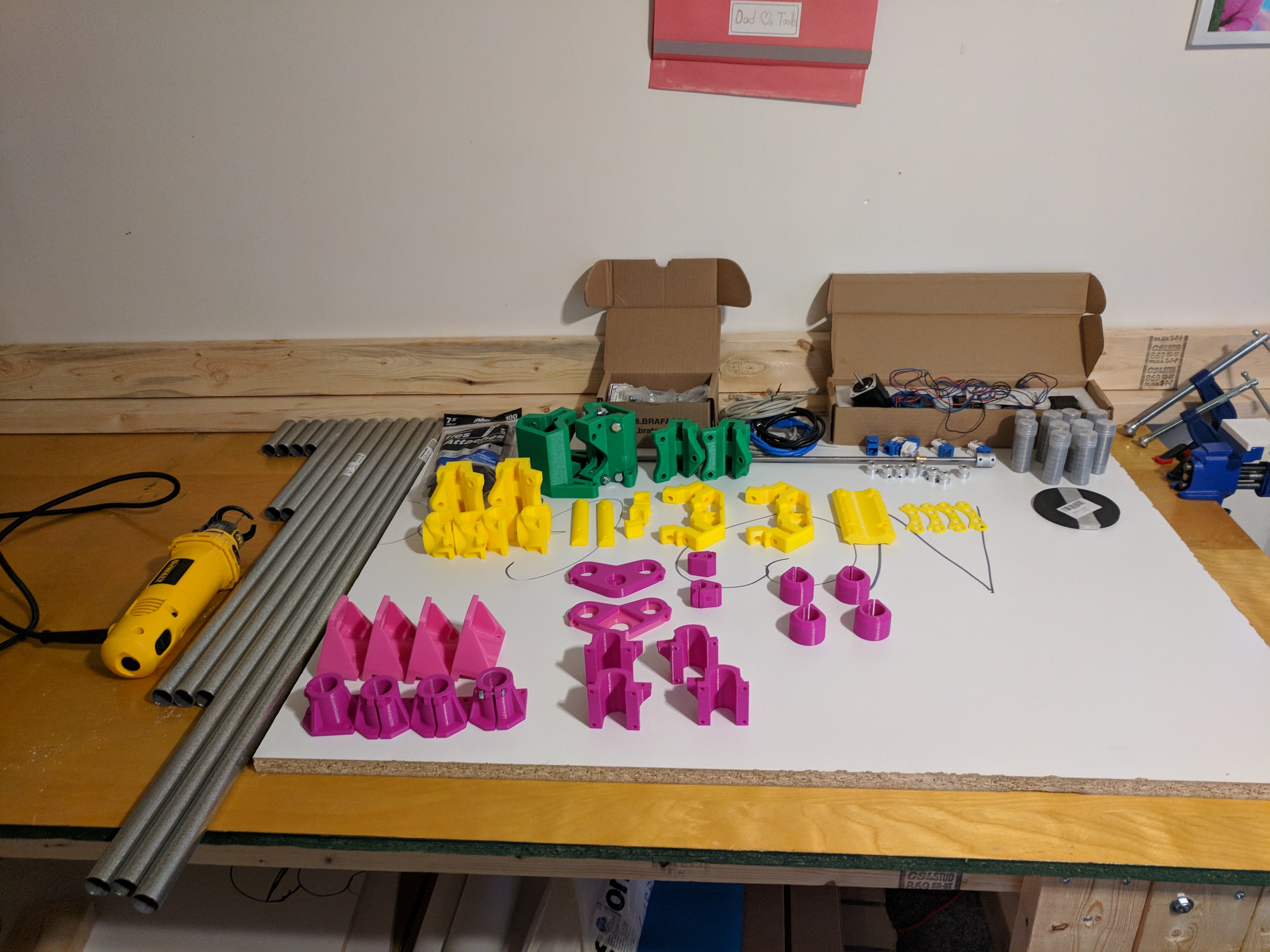
Electrical and Mechanical Parts
The parts needed are pretty well documented on the MPCNC website.
I went with imperial bolts since they are easier to get in Canada. Go to an actual supply store like Brafasco, not Lowes or Home Depot for the nuts and bolts - they will be much, much cheaper there. Hope depot wanted $3 for a 6 pack of nylock nuts. Brafasco was around $5 for a 100 pack.
The Dewalt 660 cutout tool, bearings, stepper motors, belts, pulleys and leadscrew all came from Amazon.ca. Most of them can be had cheaper from Chinese websites, but I’m impatient and had an Amazon gift card to use up.
I already had the RAMPS board and Arduino as spares for my 3D printer. The entire kit from FastTech was around $40 USD.
The EMT came from Lowes. Also a shop vac, a couple types of squares and some clamps. I used some 3/4” laminated particleboard I got dirt cheap from the Restore store. While I was there I also found a huge sheet of T slot board for $8. Had a big crack in it, but since I just need small sections it’s perfect for my use. That will be my spoil board and let me slot clamps into it.
Printed Parts
Printing all the parts took a lot of time and filament. I’m using a Wanhao i3 printer. I tried to work out the printing order to use up as much of the partial spools I had lying around as possible (which is why my MPCNC is such a random assortment of colours). Altogether, it took roughly 2.5 1kg spools and a week or so of printing time.
Sizing Considerations
I went back and forth on this a few times. The machine can easily be any size up to 42x42 (even bigger with some reinforcement in the middle). But bigger isn’t always better.
Some considerations I had to think about:
- I want the work area to be at least 24” in one dimension. It’s easy to get 2’x4’ sheets of various boards, and that way I just need to cut them in one direction before putting them in the machine.
- Smaller means the frame is much more rigid and should give better results.
- How much table/room space am I going to dedicate to this thing?
- How big is the board I am mounting it on?
- Will I be able to move it around without having to completely disassemble it? Can I get it through the door in one piece?
I ended up going for an approximate 25”x16” working area. That required a base of at least 36”x27”. The particle board I had was 30”x60”, so I could easily cut it to size. It fits on my workbench nicely.
Mechanical Assembly
Basically I just followed the guide on the MPCNC website. It’s pretty well written.
Wiring
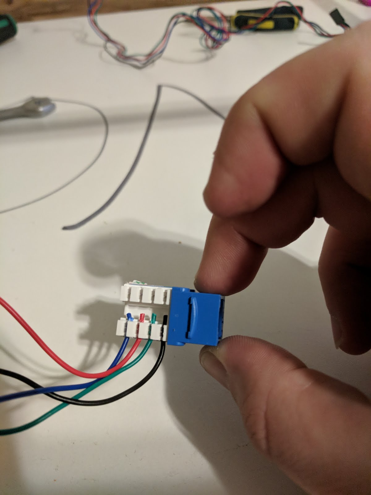
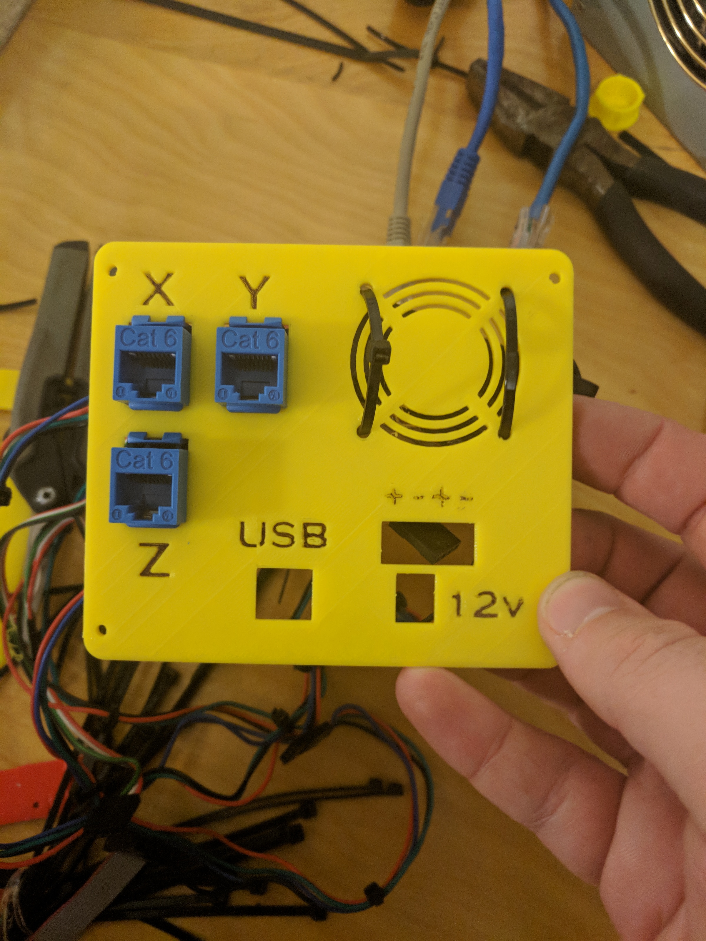
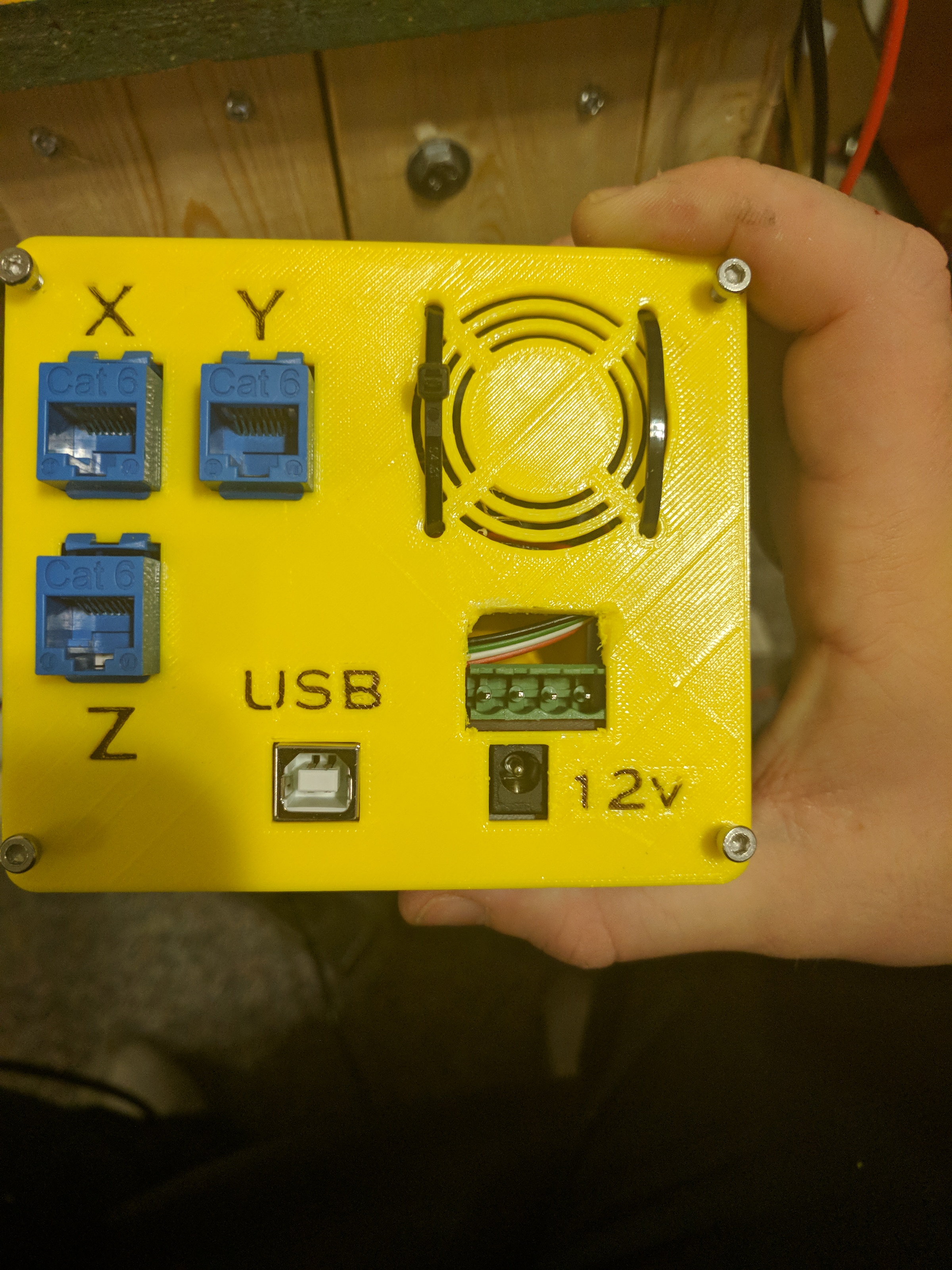
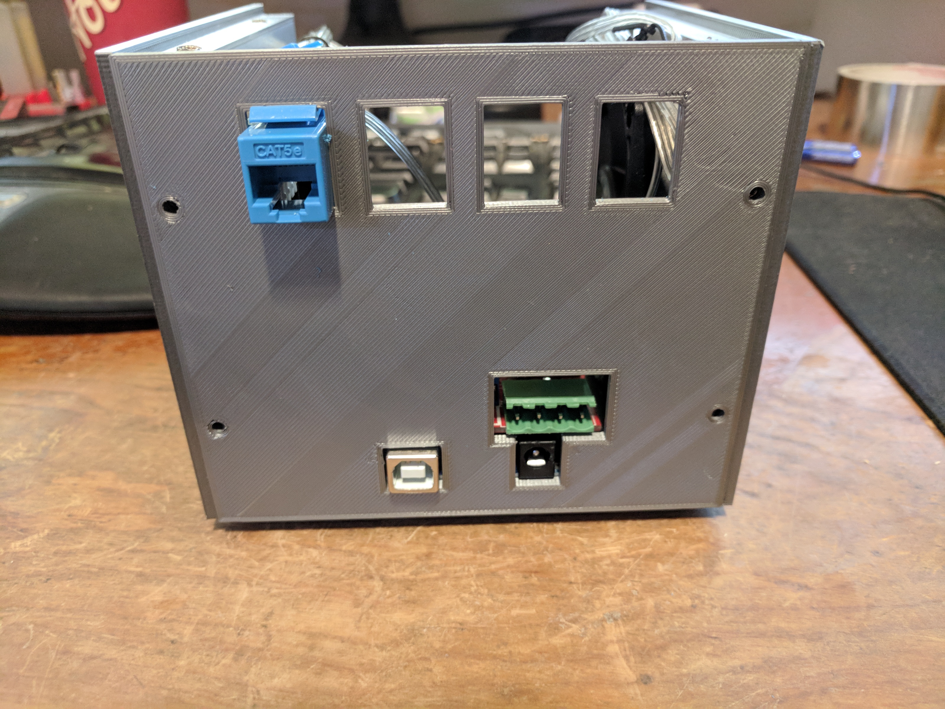
Here I deviated from the instructions. I want to use ethernet cables to connect the control box so I can easily disconnect it. People had made brackets for previous versions of the MPCNC to add keystone jacks, but they are no longer compatible. So I’ve created some of my own.
I also decided not to wire the steppers in parallel or series, but rather run each one back to the control box separately. This lets me add individual end stops later if the firmware ends up supporting it at some point. It also means I’m spreading the load for the stepper drivers across 5 drivers instead of 3. Downside is that means there is no room to add an extruder or anything later, but I already have a 3D printer.
I was hesitant about using a single wire in the ethernet cable for each stepper wire, but after testing it for awhile it seems to work fine. That means I can use just a single jack for each axis.
Z Axis
For the Z axis, I created a holder that will fit inside the EMT and have a keystone jack pop into it. Drill a hole in the side to feed the wires in and punch them down to the keystone jack.
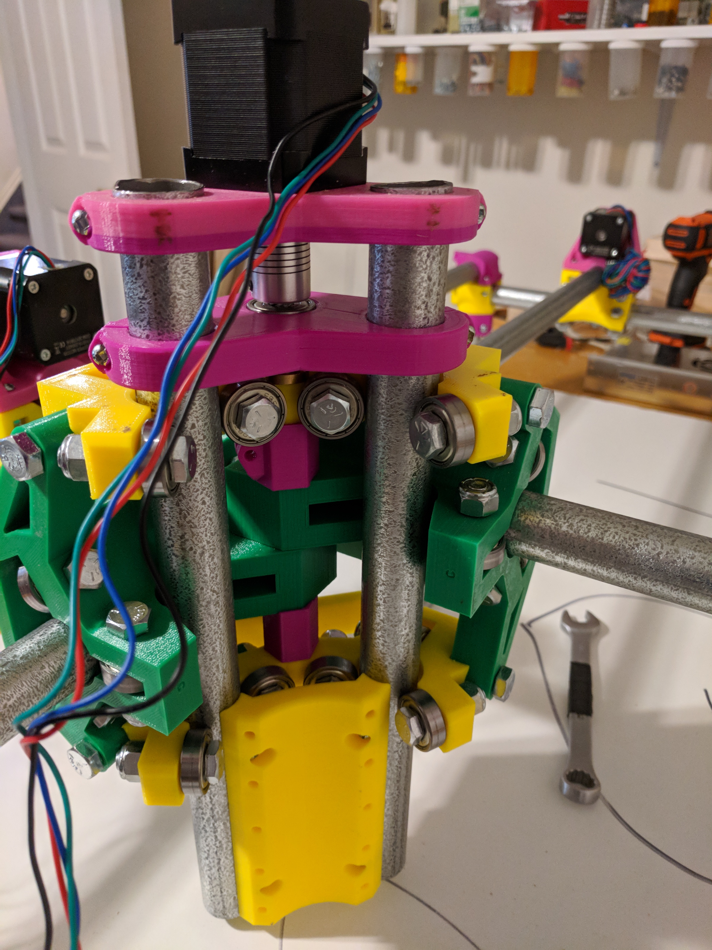
X and Y Axes
First decide which side you want the control box on. Then on the front and opposite side, run the wires for the stepper motor through the tube to the other side. Mine were a little too short, so I extended them with some 4 pin male dupont headers, and taped the connectors together so they didn’t come apart in the tube. To feed the wires through, I taped them to the end of an ethernet cable and pushed the ethernet cable through. The stepper wires aren’t stiff enough to feed through on their own.
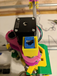
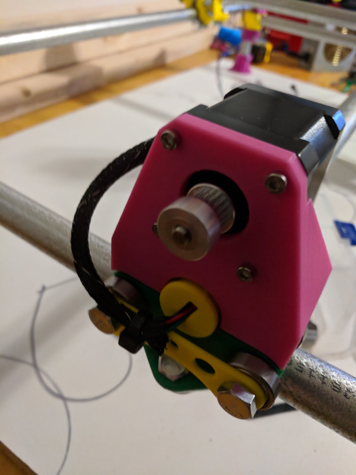
I printed some nice end caps (be sure to put them on before feeding the wire through the tube), and some wire loom to keep the cables tidy. Make sure the wires end up with a loop that won’t interfere with the belts once they are installed. Run a zip tie through the bottom of the bracket (yellow in my picture) to hold them in place. If you put the zip tie around the top of the bracket it will rub on the belt.
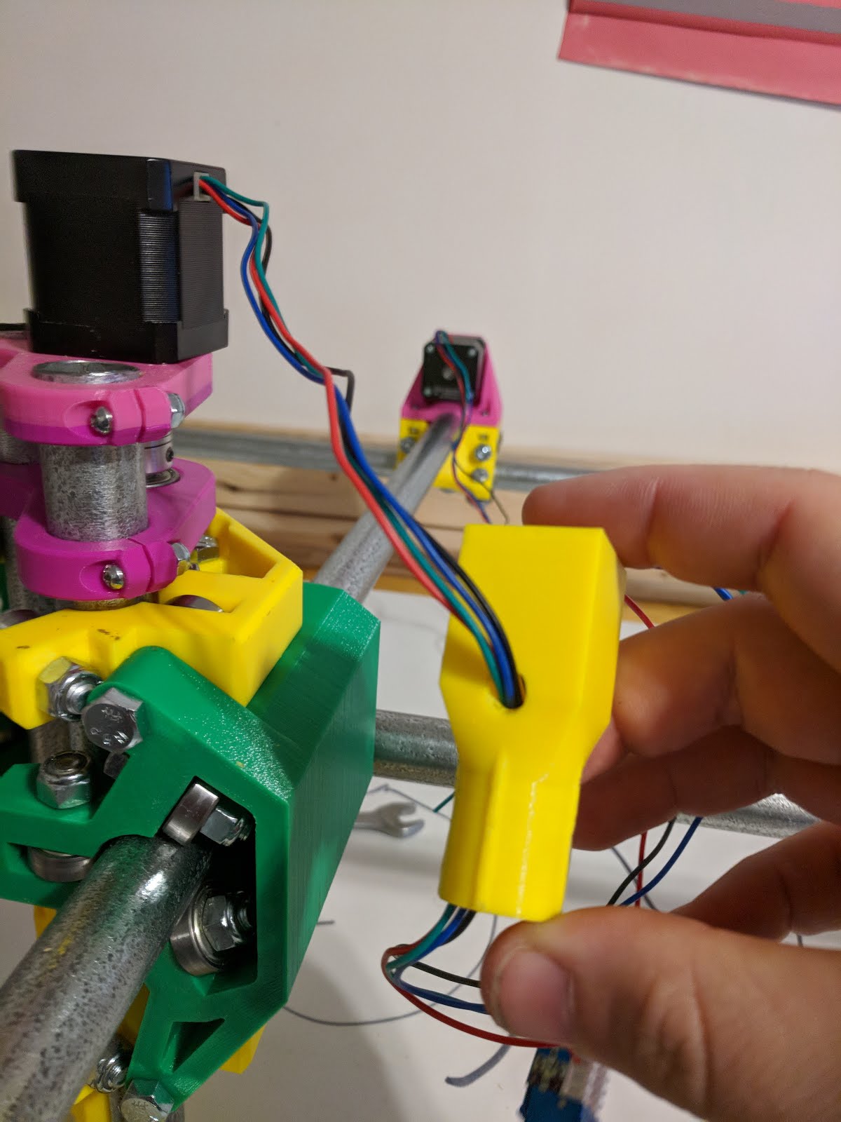
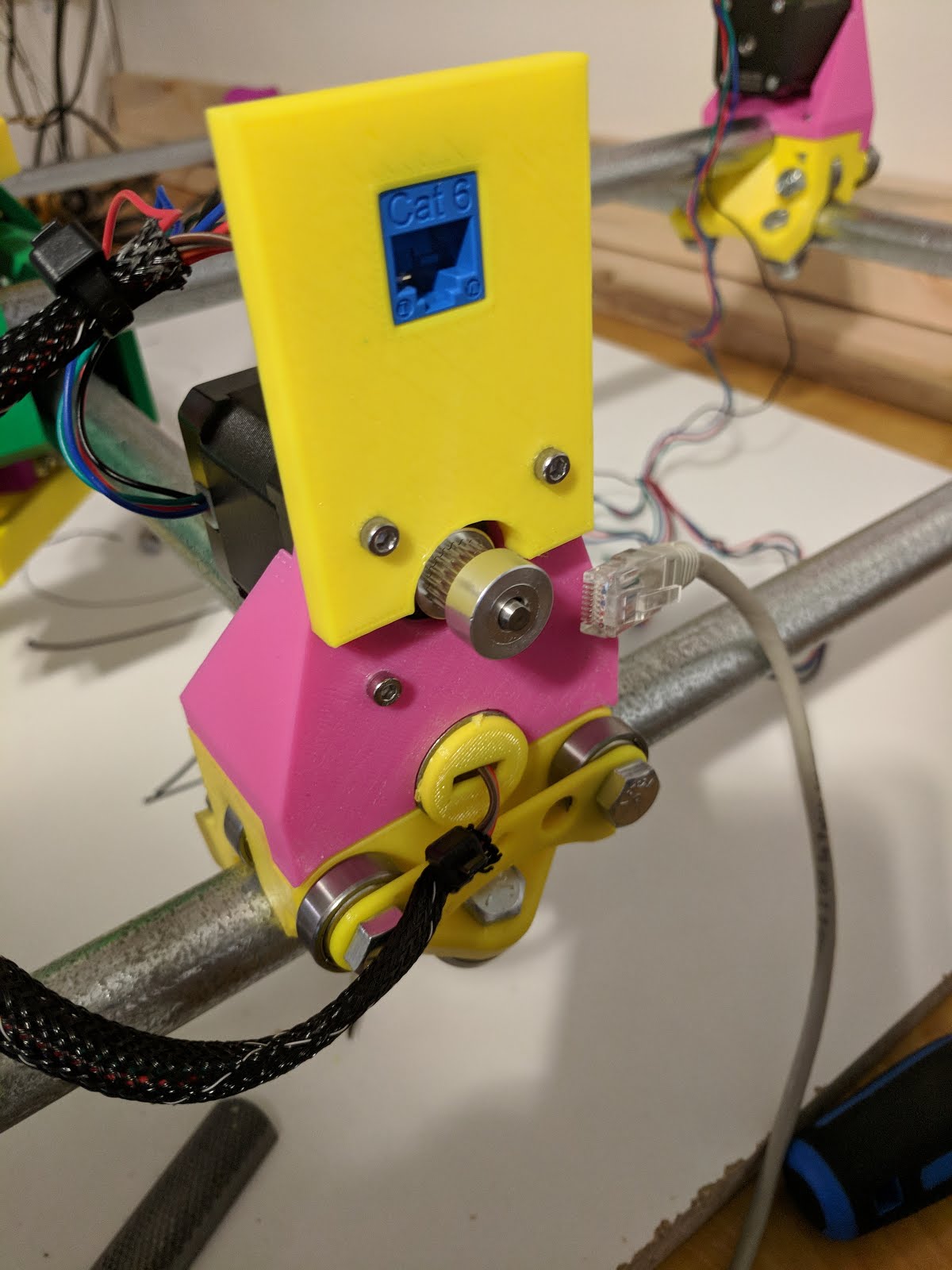
For the back and side near the control box, I wanted to mount keystone jacks. I printed this part only to realize it won’t work with the newer version - the bracket between the two bearings is in the way, so it can’t be inserted in the tube.
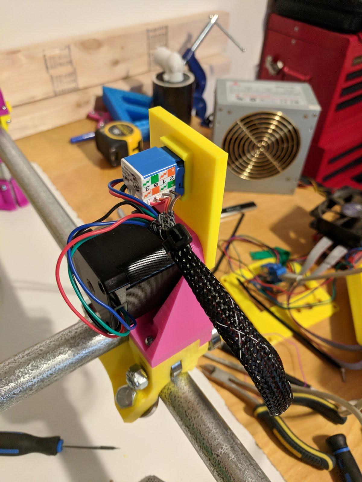
Instead I created a part that mounts above the stepper and fits a keystone jack. This requires replacing the two top M3 screws with slightly longer ones to hold the stepper in place. I think the ones I used are 16mm long.
Each stepper is punched down to one side of the keystone jack. The slack wire from the close stepper is shoved in the wire loom to keep it out of the way.
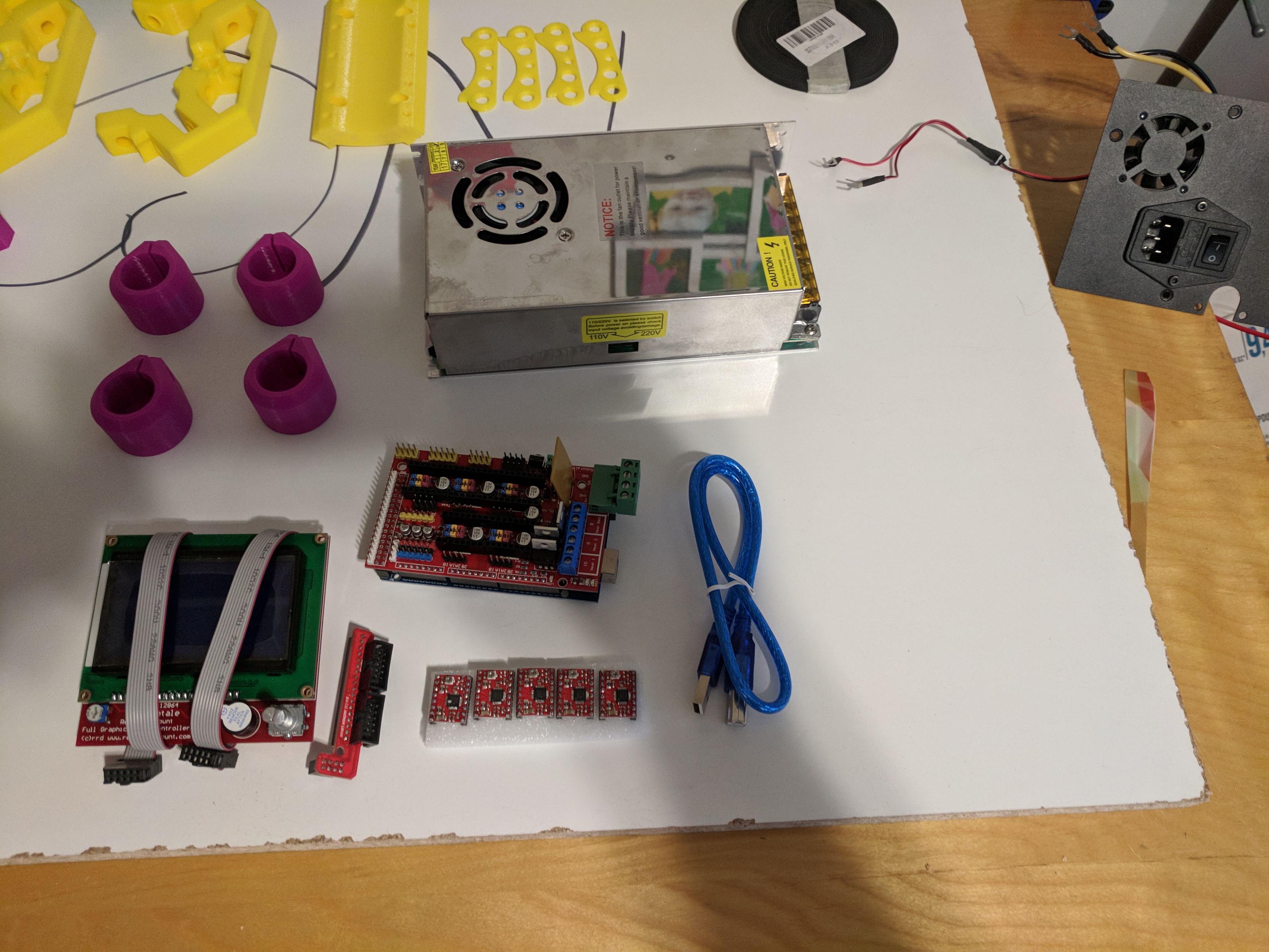
Control Box
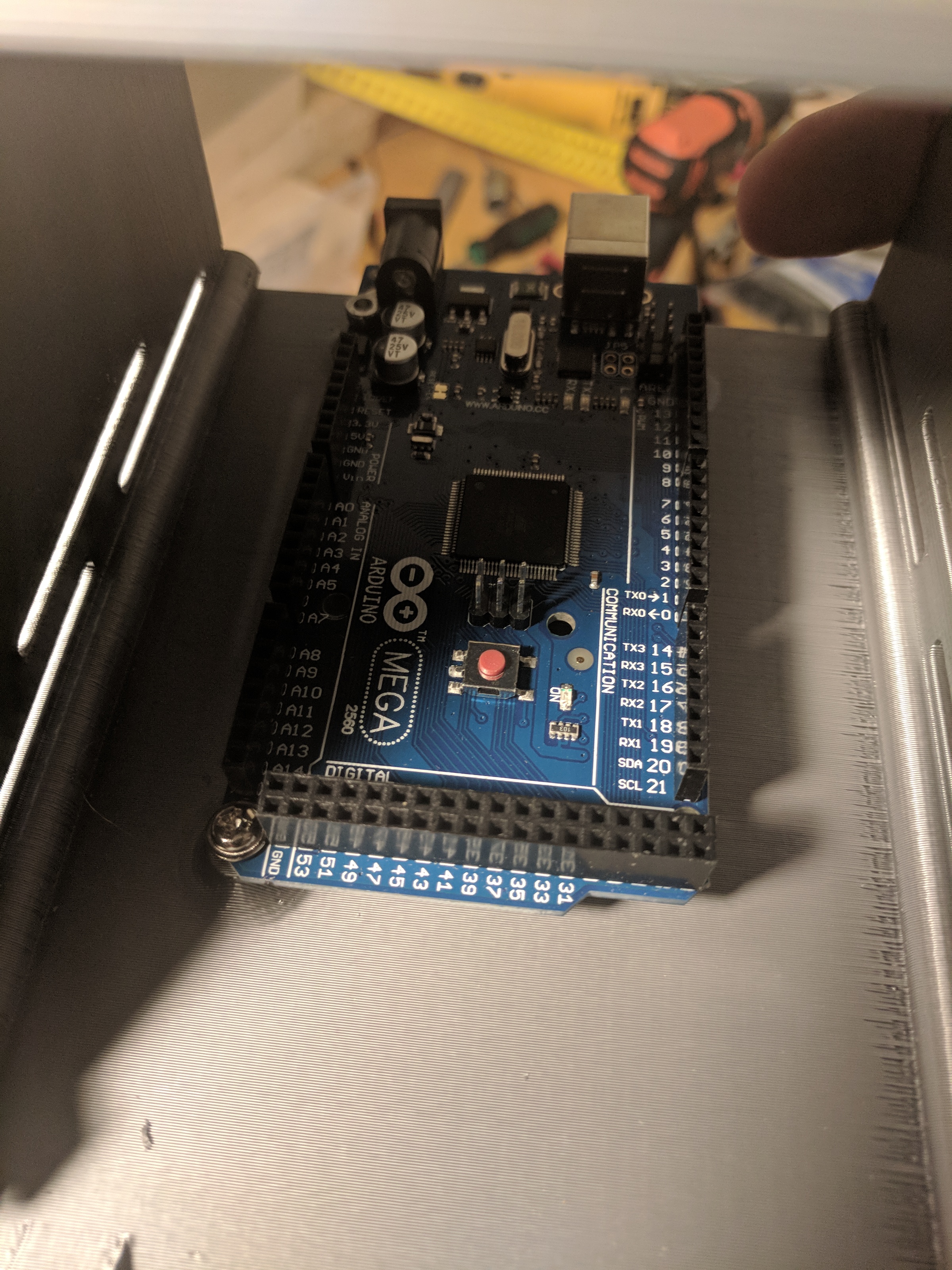
I’m using an arduino with a RAMPS 1.4 board.
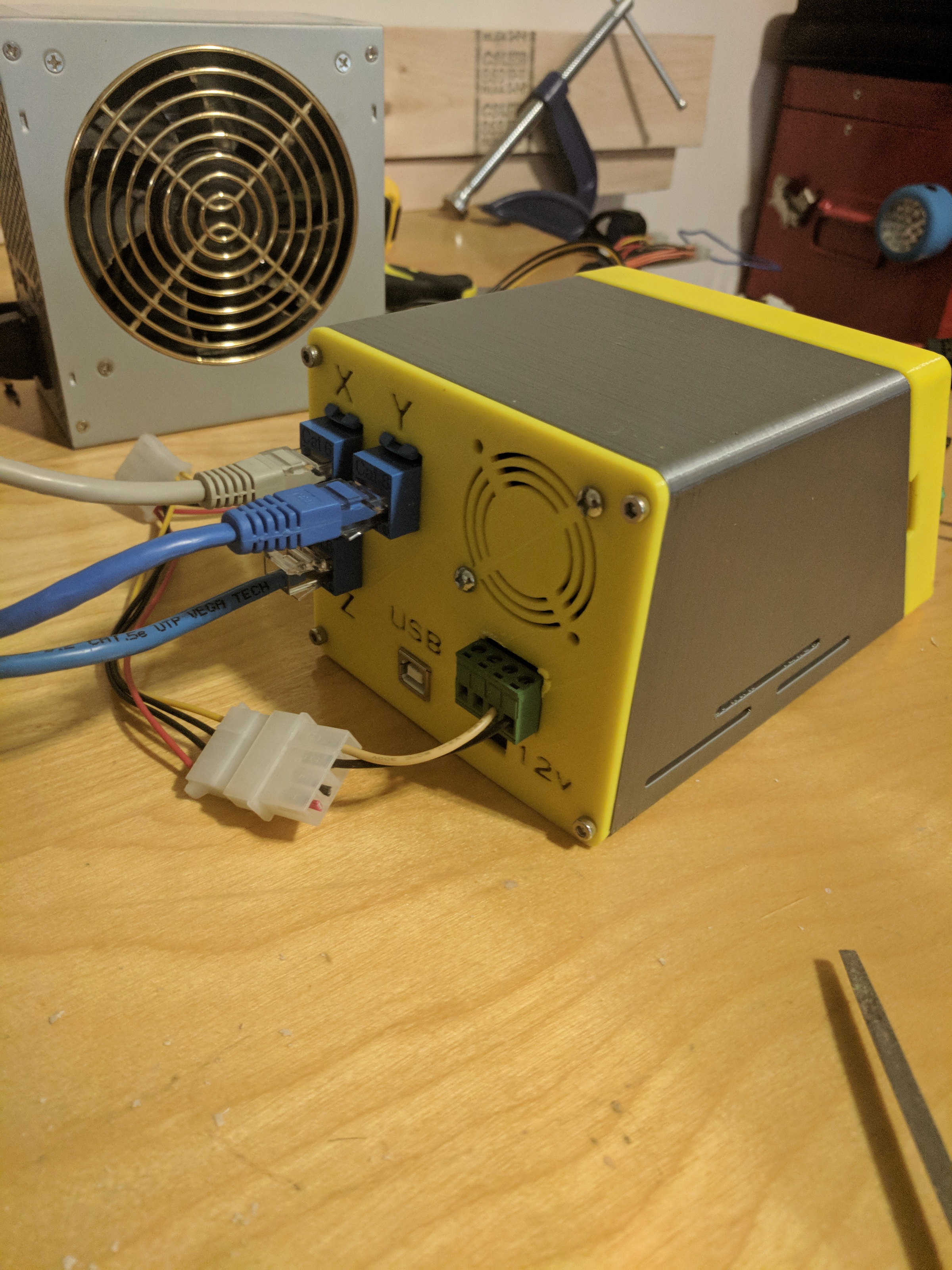
The case is this one that I 3D printed. The screw holes all got M3 knurled inserts heat pressed into the plastic with a soldering iron. The power connector wouldn’t fit in the case. Instead of fixing the design and reprinting it I decided to just hack at it until it fit.
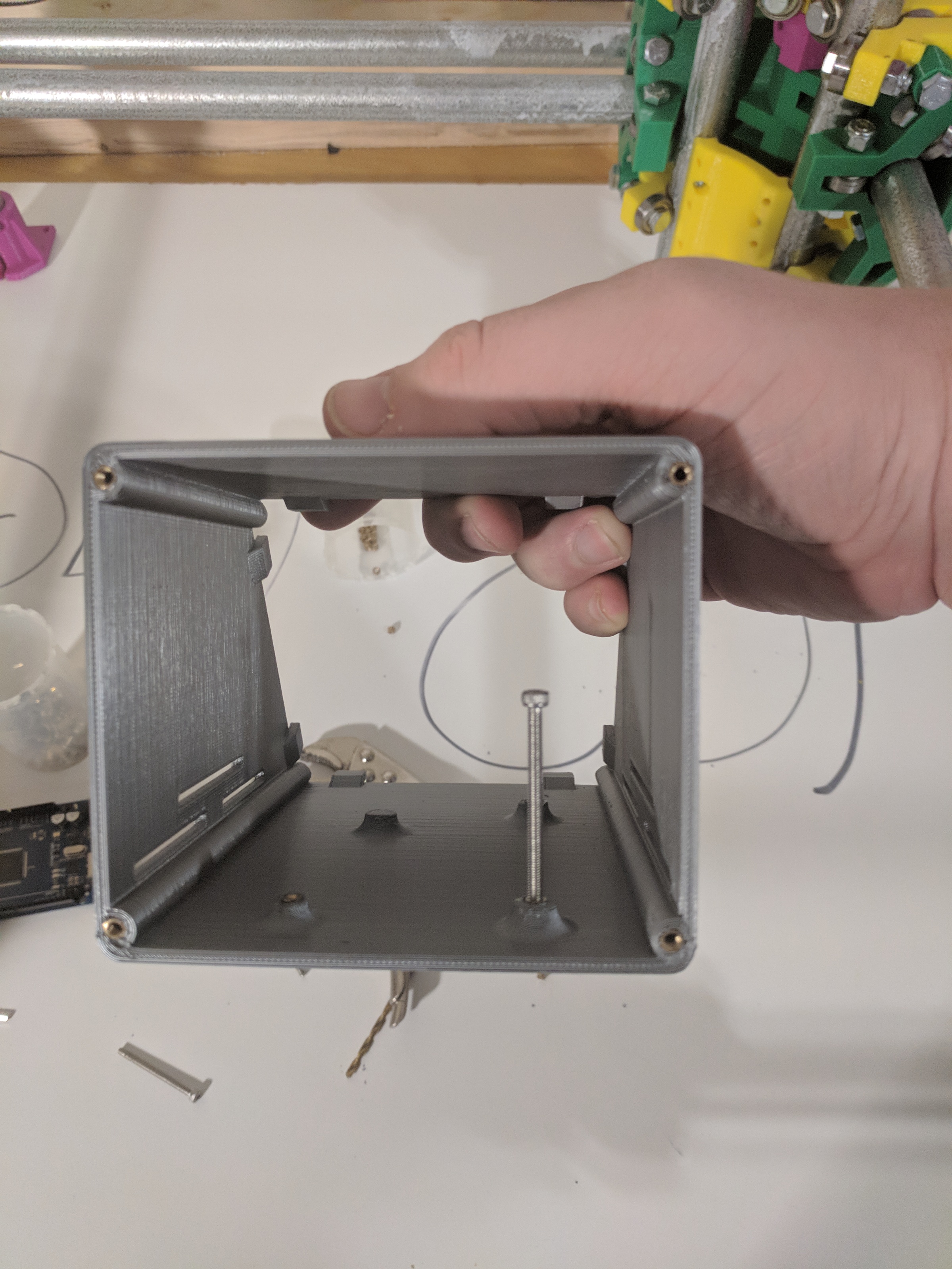


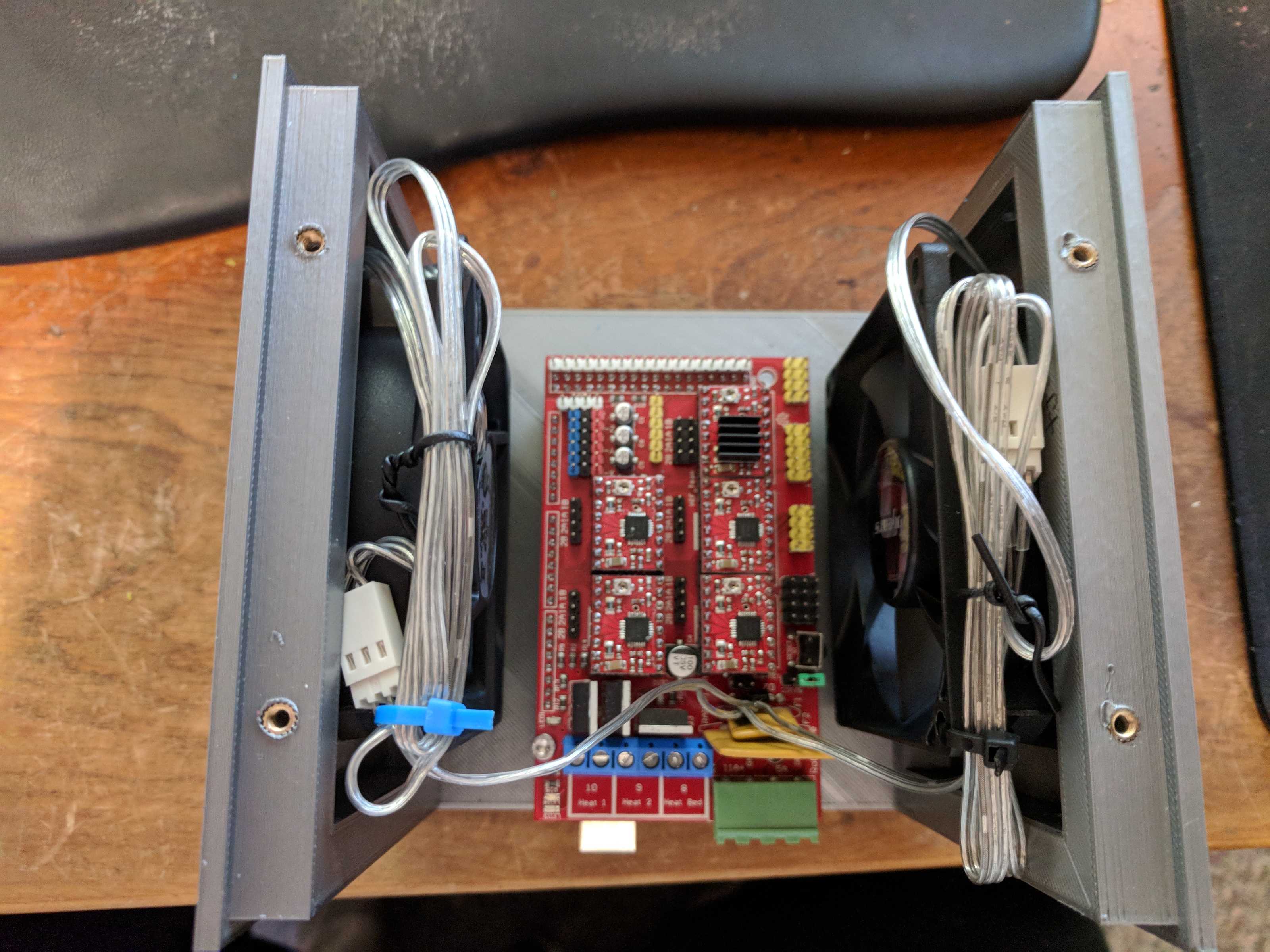
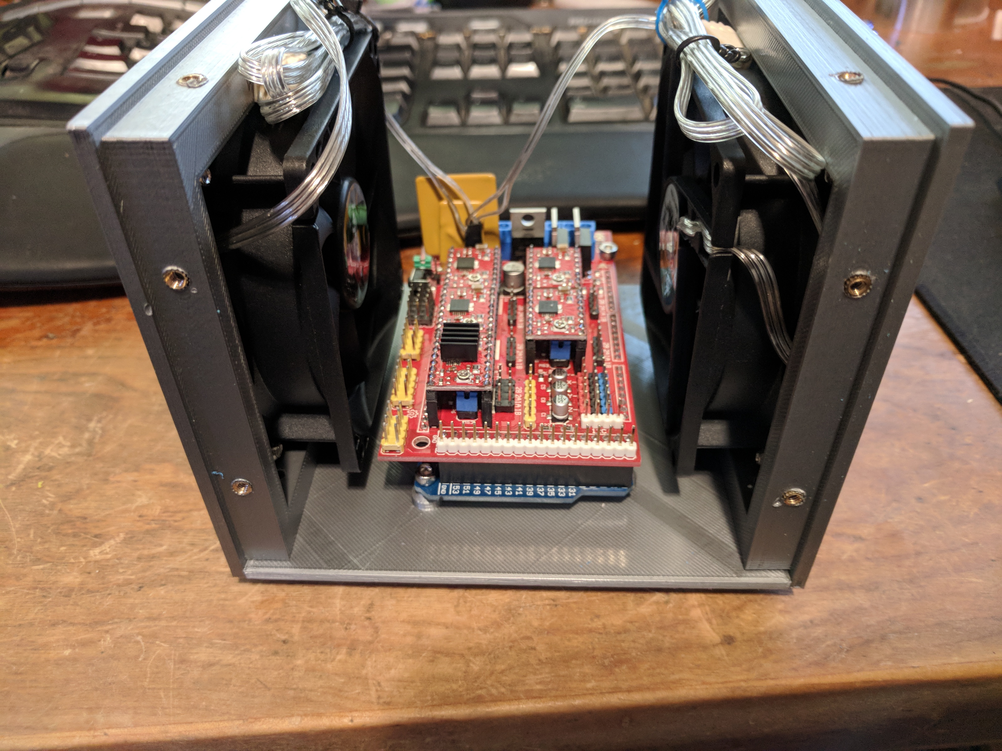
Control Box 2
Of course, soon after putting the control box together, I realized it had some issues. First off, the display never fit quite right, and actually damaged the solder connections for the screen when I tried to force it in place. It still worked, but only if pressed in at just the right angle.
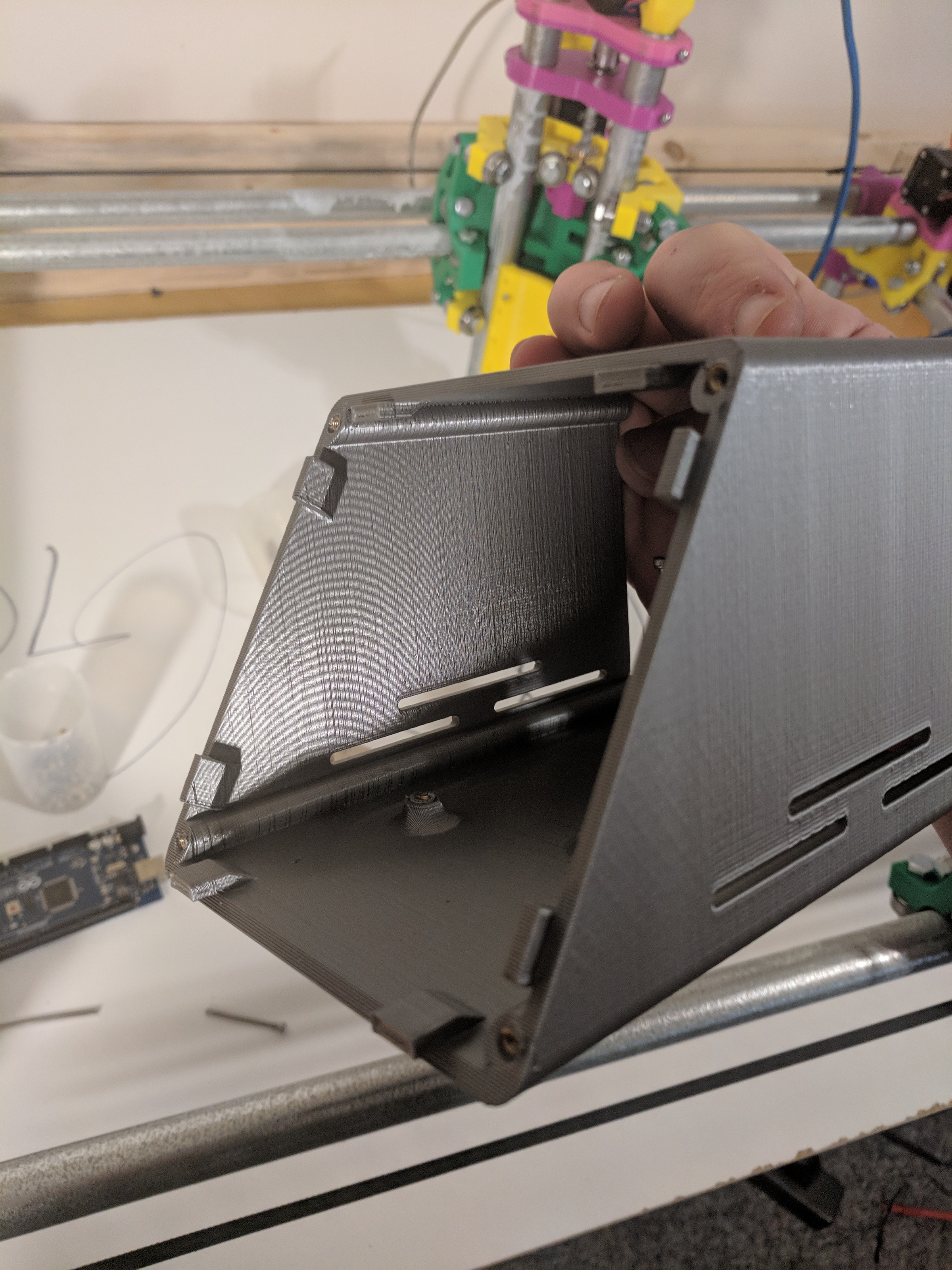
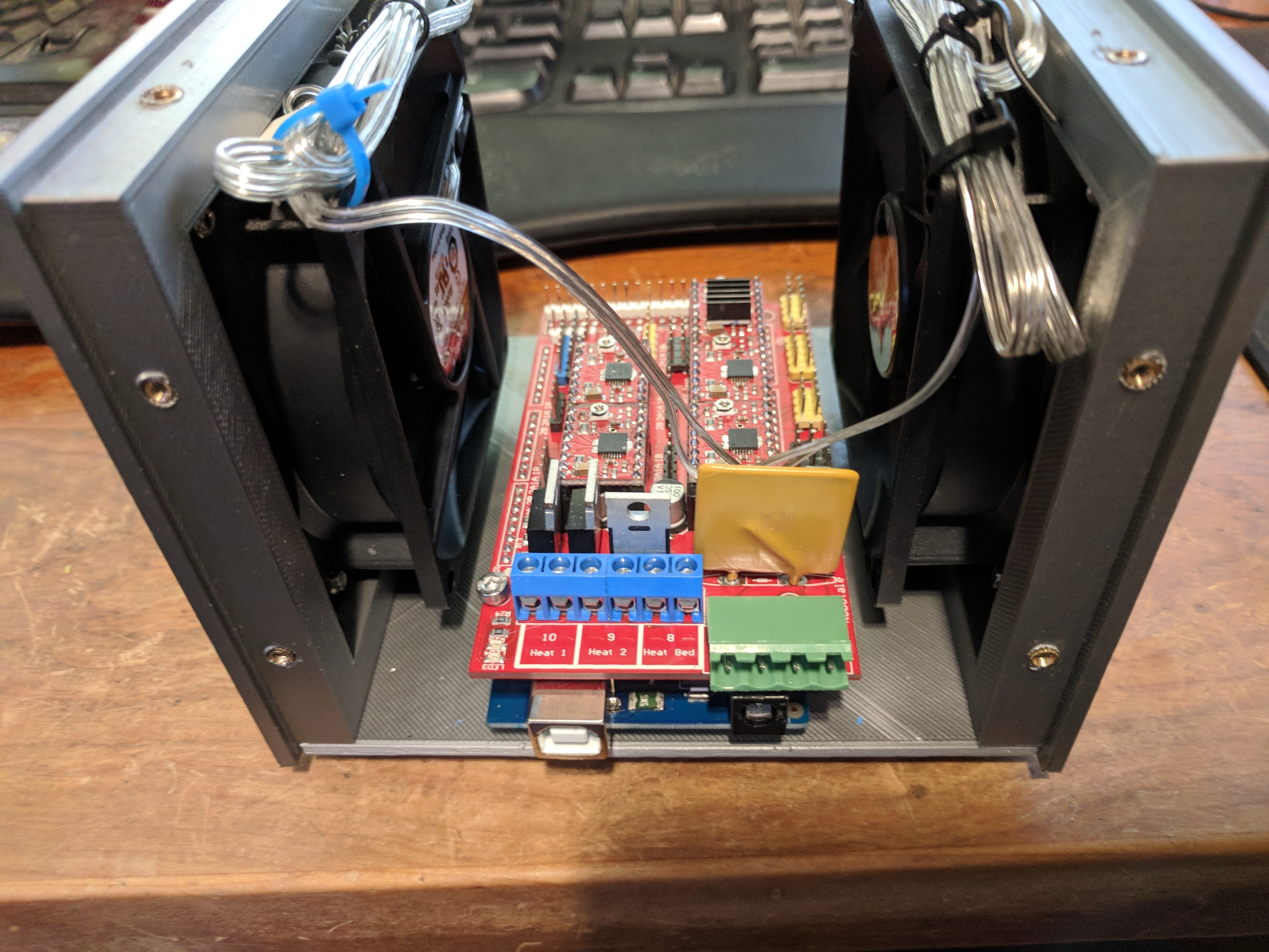
On top of that, there wasn’t enough cooling in the box. Stepper drivers get hot.
So I designed my own case and reassembled it. This one features 2 nice 80mm fans. I haven’t uploaded the designs to thingiverse yet.

First Run
The first run was done with a sharpie and this pen holder.
